A facade corner detail is the drawn resolution of what happens where two elevations of a cladding system meet at an external arris — whether the module is mitred, returned around the corner, stopped against a corner post, rebated back from the edge, or terminated into a reveal. It is settled in millimetres on a setting-out drawing, and it is settled before the pattern is frozen. Most facade patterns are designed on a flat elevation, where the module repeats at a fixed pitch and every small error is swallowed by the joint. The corner swallows nothing. It is the one place on a building where two independent setting-out grids, an arris read obliquely over the full height, and a bracket that has to work in two directions all arrive at the same 200 mm of edge. What follows is the five real corner moves, what each costs to fabricate, what tolerance each demands of the frame, and how each one fails on site.
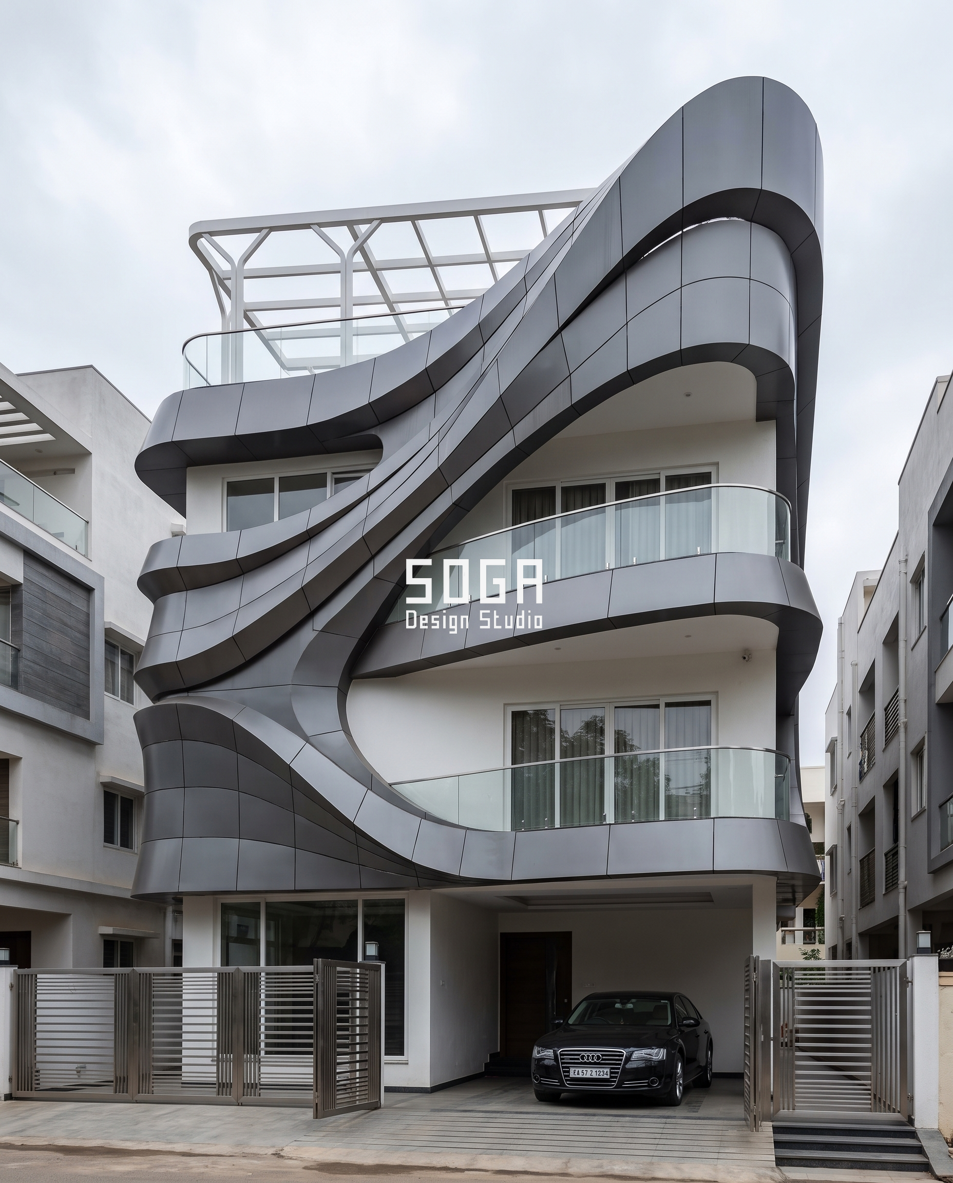
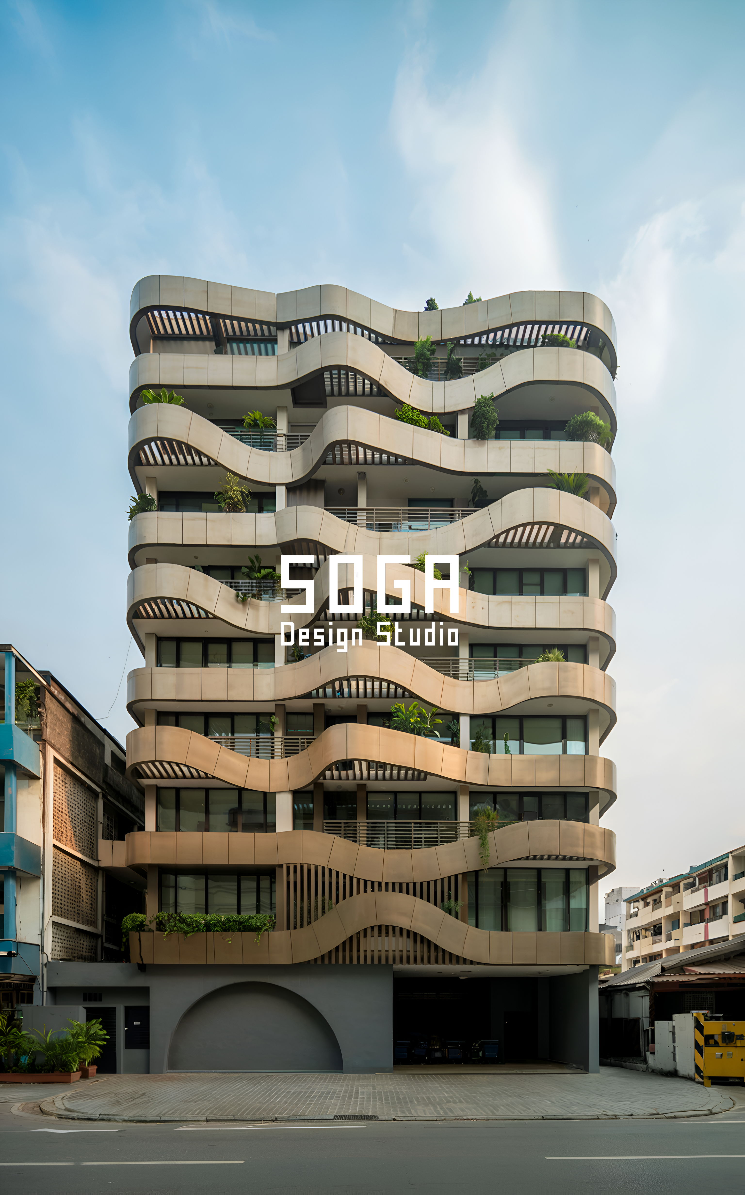
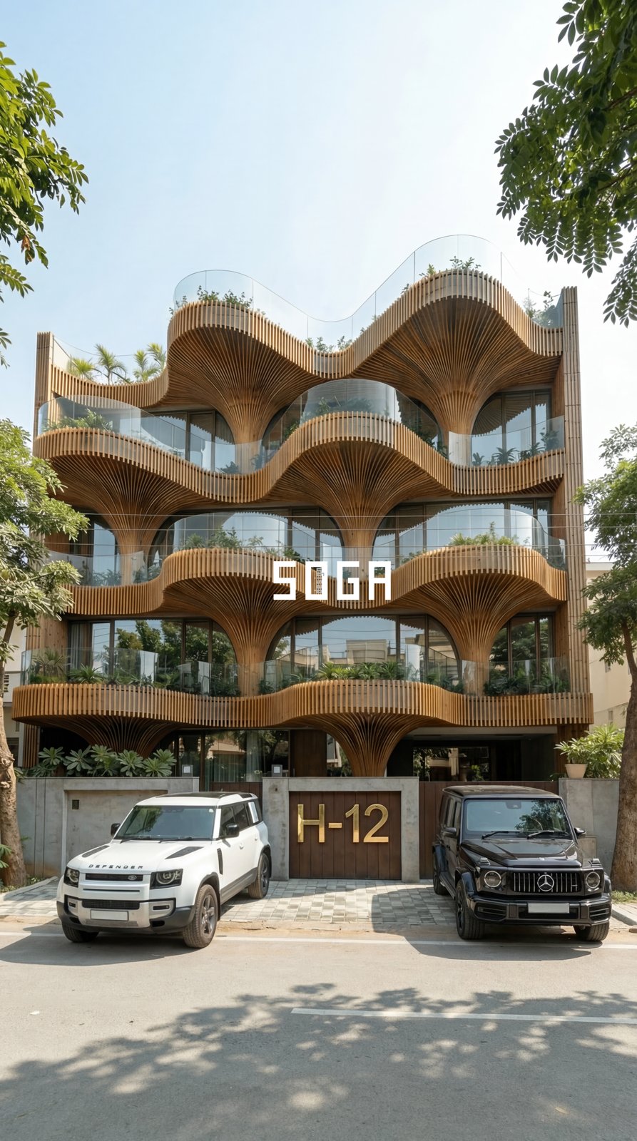
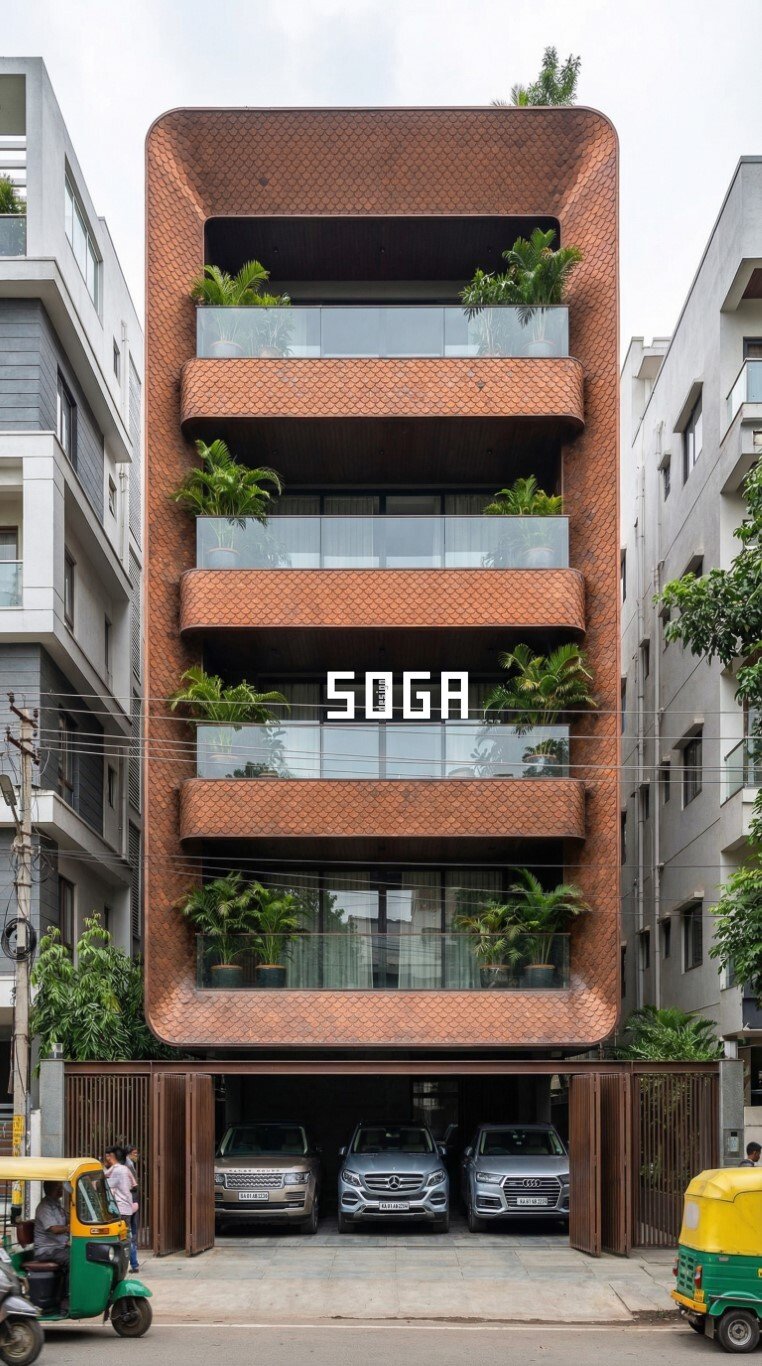
Images on this page show SOGA Design Studio facade systems. The set includes both project photography and design visualisations; no individual image should be read as a claim that a particular building is complete.
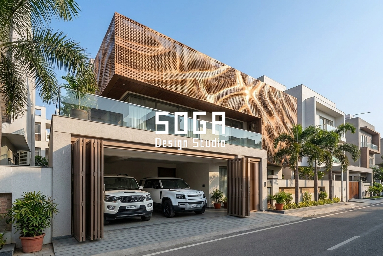
What does a facade corner detail actually have to resolve?
Five things, and on a well-run job they are resolved in this order: the position of the arris relative to the structural grid; which of the two elevations carries a whole module; how the module face returns, or refuses to return, onto the second plane; how wind load leaves an edge that has primary structure on one side only; and how the two drainage planes are joined. Pattern is decided after those five, not before. Design the pattern first and then ask the corner to accept it, and you pay for that decision twice — once in bespoke parts and once in site rework.
A facade corner detail resolves arris position against the structural grid, which elevation carries the whole module, how the module face returns onto the second plane, how wind load leaves a one-sided edge, and how two drainage planes are joined. Pattern follows from those decisions rather than driving them.
- Arris position is set from the RCC face, not from the finished cladding line. A 25 mm structural deviation at the corner becomes a 25 mm pattern deviation on both elevations at once.
- Module ownership decides which elevation reads as continuous. One of them will be cut. Choose it deliberately, from the approach view, rather than letting the fabricator choose it at 2 a.m.
- Return geometry determines whether you are buying a folded part, a mitred pair, an extrusion, or nothing at all.
- Load path at a corner is asymmetric. The bracket on the leading leg cantilevers past the slab edge and takes suction from two directions.
- Water and air stop at the corner. Two drainage planes have to be tied together with a continuous seal, and the corner is where a drained-and-back-ventilated cavity is most often left open by accident.
If you are working with a depth-based module system, the corner arithmetic is different again, because the module has a third dimension to resolve as well as a pitch — the SOGA 3D Block facade guide sets out how depth is scheduled per panel, and that schedule has to carry a separate corner family.
How many ways can a facade actually turn a corner?
Five, and every corner you have ever looked at is one of them or a hybrid of two. Mitre the module so the two faces meet at the arris. Return the module bodily around the corner as one folded piece. Stop both elevations against a corner post or stop-end. Rebate the module back from the arris so the corner is a recessed shadow line. Or let the pattern die into a reveal a fixed distance short of the corner and clad the last strip in plain sheet. Everything else is a variation on pitch, depth or material.
| Corner move | What happens at the arris | Relative fabrication cost | Setting-out tolerance demanded | How it fails on site |
|---|---|---|---|---|
| Mitred | Two module faces meet on a shared 90° line; no third part | 1.6–2.2× a flat-elevation module | ±1.0 mm on the visible gap; ±3 mm on the carrier | Open mitre. A 3 mm gap at eye level reads as a defect from 20 m |
| Returned / wrapped | One folded module carries both faces; leg lengths 150–450 mm | 1.4–1.9× | ±2 mm on leg length; ±4 mm on carrier | Twist. A long folded leg loses squareness and the second face bows |
| Corner post / stop-end | Both elevations butt into a separate extruded or folded post 60–180 mm wide | 1.0–1.3× | ±5 mm; the post absorbs the error | Post reads as a foreign object if its width is not tied to the module pitch |
| Module rebate | Pattern stops 40–120 mm short; the corner is a recessed plain band | 1.0–1.2× | ±6 mm; the rebate hides the deviation | Rebate depth too shallow — the shadow disappears in flat overcast light |
| Die into a reveal | Pattern terminates against a 25–60 mm deep reveal; last bay is plain | 0.9–1.1× | ±8 mm; the most forgiving of the five | Reads as an unfinished edge if the reveal is narrower than the module depth |
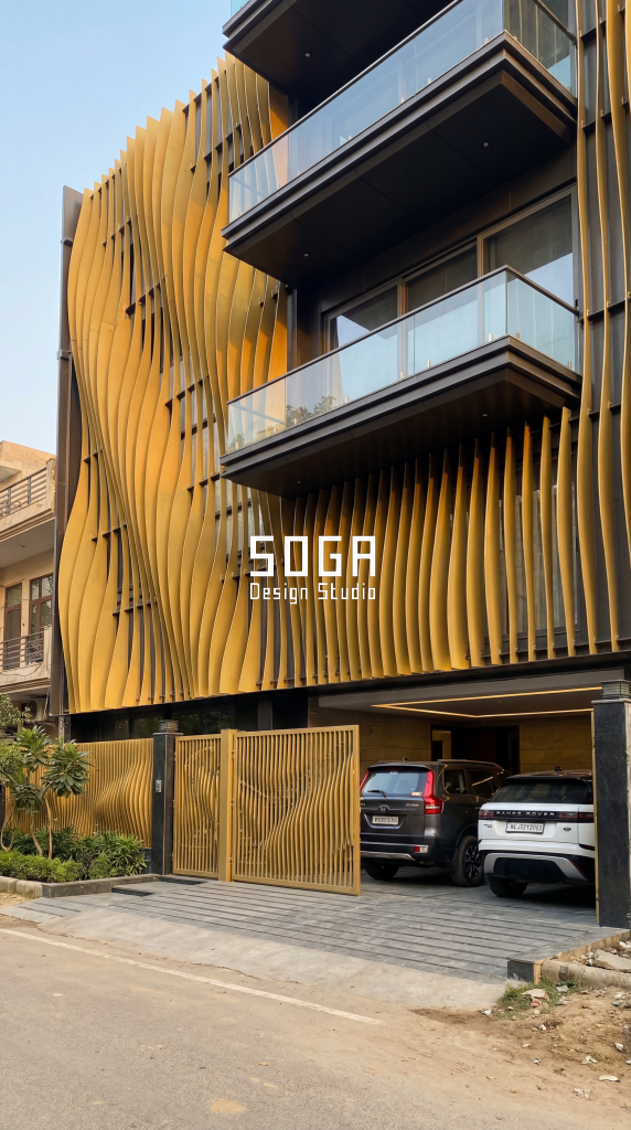
The cost column is the honest reason most corners end up as posts and reveals. The tolerance column is the honest reason most mitres end up regretted. Neither is a reason to avoid a mitre — it is a reason to price the frame survey alongside it.
When is a mitred facade corner the right answer?
When the module has a flat, readable face, the corner is at eye level or on the principal approach, and the structural frame can be surveyed and shimmed before fabrication is released. A mitre is the only move that makes the pattern appear to pass through the corner without interruption, and on a strong geometric module that continuity is the whole point. It is also the move with the least forgiveness in the entire cladding package.
A mitred facade corner is the correct detail when the module face is flat, the corner is seen at close range, and the frame can be surveyed before fabrication release. It is the only move that reads as uninterrupted pattern, and the only one where a 3 mm error is visible from 20 metres.
The numbers a mitred corner is drawn to
- Plate 2.5–3.0 mm formed metal for modules up to 900 mm on the long side; 3.0–4.0 mm above that, purely to hold the mitre line straight.
- Mitre angle 45° each leg, with a 0.4–0.6 mm land at the arris rather than a knife edge. A knife-edge mitre chips in transit and cannot be anodised evenly.
- Internal stiffener a 40 × 40 × 3 mm angle or a formed rib set back 30–50 mm from the arris, welded or riveted at 250–300 mm centres, so the mitre cannot open under thermal load.
- Return leg minimum 120 mm on each face. Below that the mitre has no material to stiffen against and will read as a wavy line.
- Target visible gap 1.0 mm, with 1.5 mm as the rejection threshold at close range and 2.0 mm above 12 m.
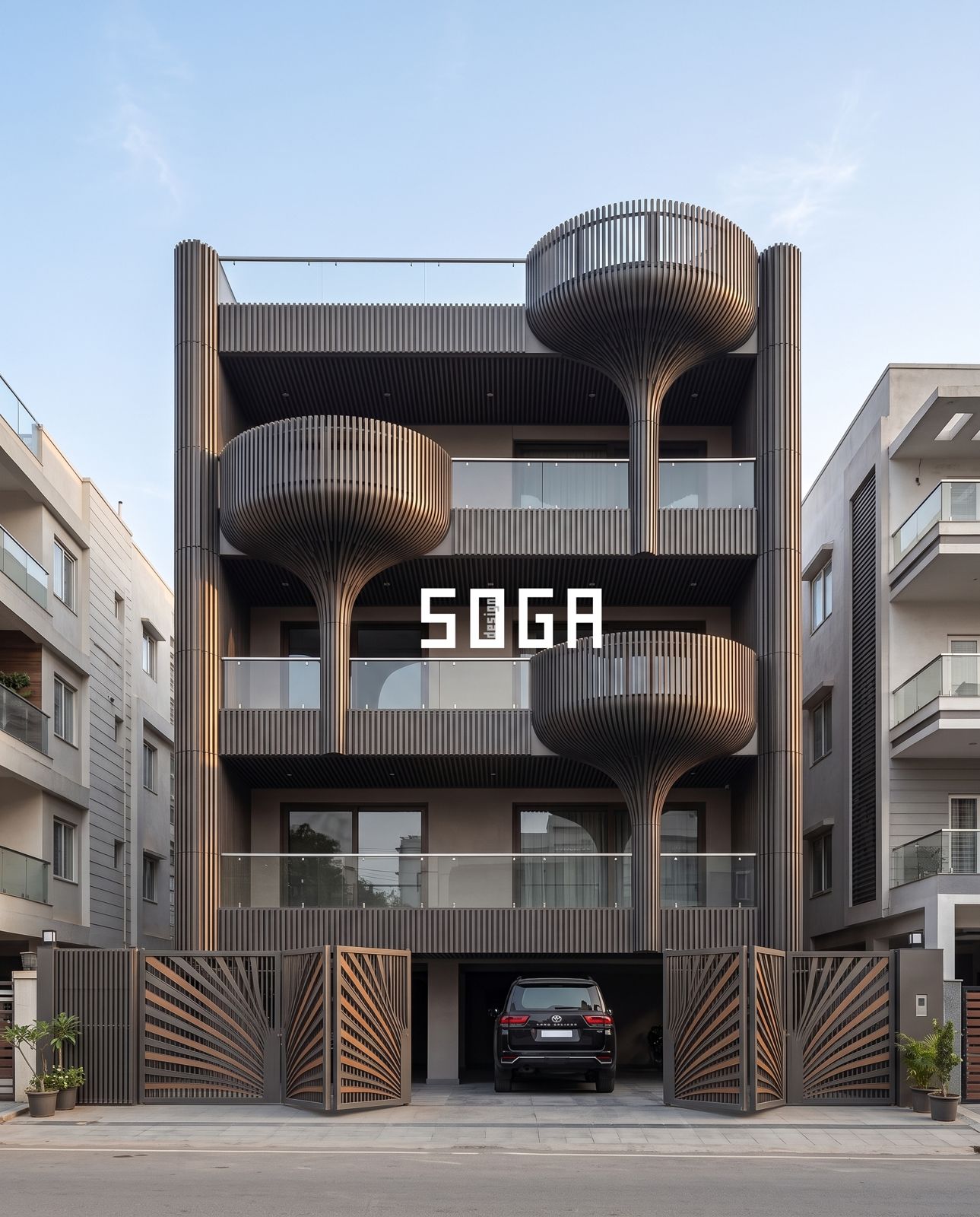
Two practical consequences. First, a mitred module is a different part number from the flat module — it gets its own drawing, its own first-article check and its own line in the schedule, even where its face geometry is identical. Second, it usually has to be fabricated late, after the frame survey, which means the corner is on the critical path even though it is perhaps 3% of the facade area. Sequencing that properly is the same discipline described in the SOGA facade fabrication record.
What tolerance does a mitred corner really demand of the frame?
More than the frame will give you, which is why the adjustment has to be designed into the bracket rather than hoped for. The arithmetic is a stack: every layer between the concrete and the visible arris either absorbs deviation or passes it on. If the stack cannot absorb the RCC deviation, the mitre opens.
| Layer | Realistic as-built deviation | Adjustment available | Deviation passed to the next layer |
|---|---|---|---|
| RCC corner as cast (in-situ, India / Gulf typical) | ±20 to ±30 mm in plan; up to 40 mm over 4 storeys | — | ±25 mm |
| Cast-in channel or post-fixed anchor | ±10 mm placement | Slotted, ±20 mm in two axes | ±5 mm |
| Bracket / helping hand | ±3 mm | Serrated or shimmed, ±15 mm out, ±10 mm lateral | ±2 mm |
| Carrier rail or T-section | ±2 mm over 3 m | Slotted, ±5 mm | ±1.5 mm |
| Module hook / clip | ±1 mm | ±2 mm | ±0.5 mm |
| Visible mitre gap | — | — | 1.0 mm target, 1.5 mm limit |
Read the last column upwards. A mitre asks the bracket layer to remove roughly 25 mm of concrete deviation and hand on less than 2 mm. That is achievable, but only with a three-axis adjustable bracket and a survey of the actual corner before the corner modules are cut. It is not achievable with a plain angle cleat and a set of packers found on site.
The joint gap between adjacent modules is a separate calculation driven by thermal movement and material coefficient, and it is not the same number as the mitre gap. Do not let one be substituted for the other on a shop drawing.
How does a returned or wrapped module work?
One folded part carries both faces, so there is no visible junction at the arris at all — the corner becomes a bend rather than a joint. It is the strongest-looking of the five moves and, on a curved or faceted module, often the only one that is geometrically honest. The trade is that you are now buying a part with two long legs that must stay square to each other through forming, finishing, transport and lifting.
A returned facade module is a single folded piece that carries both elevations around the arris, so the corner has no visible joint. Leg lengths of 150–450 mm are practical; beyond about 600 mm the part twists in handling and the second face bows visibly under raking light.
Practical limits on a wrapped corner module
- Leg length 150–450 mm each side is comfortable. 450–600 mm needs an internal frame. Above 600 mm, split it and mitre instead.
- Bend radius 2–3× plate thickness on a formed metal module; a 3 mm plate gives a 6–9 mm external radius, which softens the arris and is often exactly what the design wants.
- Squareness hold 90° ±0.5° on the fold. At 400 mm leg length, half a degree is 3.5 mm of wander at the free edge.
- Fixing the wrapped module must be restrained on both legs, or the unrestrained leg drums in wind. Two carriers, not one.
- Finish anodise or powder-coat after forming, never before — a formed edge on a pre-finished sheet crazes at the bend.
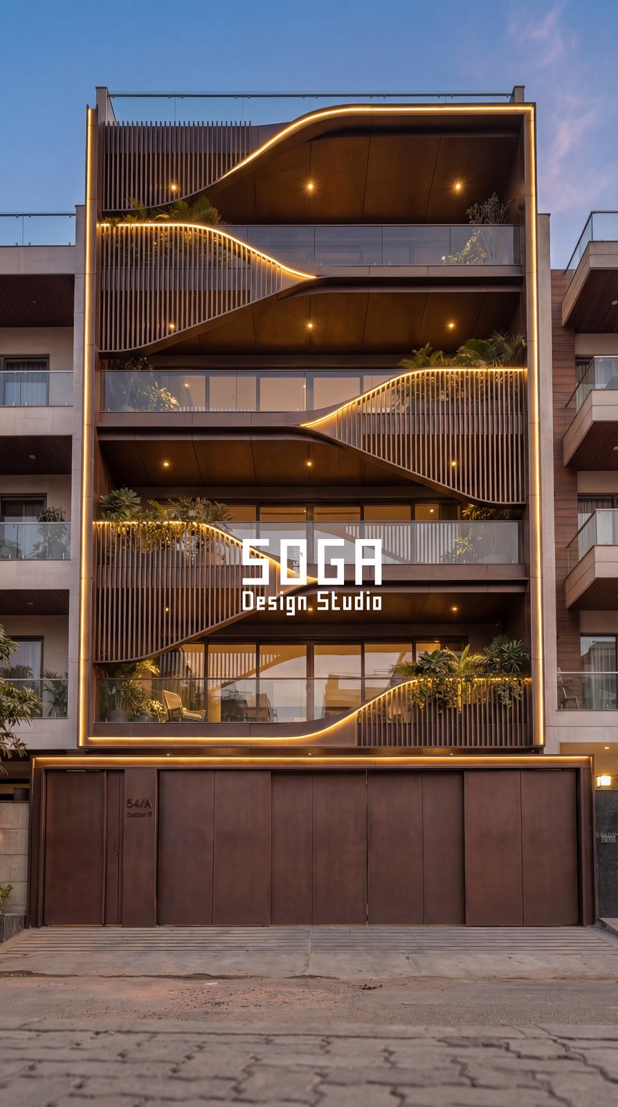
Where the module is a scale, disc or overlapping unit rather than a flat plate, the return is easier because the unit is small relative to the corner and the field simply continues around it — the logic is the same as in the SOGA Sequin facade system, where unit size is deliberately kept small enough that curvature and corners are absorbed by the field rather than by bespoke parts.
What is a corner post, and why do most projects end up with one?
A corner post is a separate vertical element — typically an extrusion or a folded box 60–180 mm wide on each face — that both elevations butt into. It is the cheapest, most forgiving and most commonly built corner in the world, and it is treated as a compromise far more often than it deserves. A corner post that is dimensionally tied to the module pitch does not read as a compromise at all; it reads as a deliberate vertical accent.
A corner post is a separate 60–180 mm wide vertical member that both elevations terminate against. It absorbs up to 5 mm of setting-out error per face, removes every bespoke corner part from the schedule, and reads as designed rather than defensive when its width is a whole fraction of the module pitch.
Making a corner post look intentional
- Tie its face width to the module pitch: at a 450 mm pitch, a 150 mm post face is a clean third; at 600 mm, 150 mm is a quarter. An arbitrary 137 mm post is what makes corner posts look like an afterthought.
- Give it a different depth from the module field — typically 20–40 mm proud or recessed — so the eye reads it as a distinct element rather than a failed module.
- Run it full height, floor to parapet, without interruption. A post that stops and restarts at each slab is the single most common reason a corner looks untidy.
- Use the same alloy and the same finish batch as the field modules. A corner post in a different anodising batch will not match, and the corner is precisely where two batches are compared side by side.
- Detail the seal inside the post, not at its edges, so the two drainage planes are joined in a single accessible line.
The corner post also solves the module-count problem described further down without any pattern gymnastics: each elevation sets out independently from its own datum and both simply stop at the post.
When should the module rebate back from the arris?
When the module has real depth and you want the corner to read as a shadow rather than as an edge. A rebate stops the patterned field 40–120 mm short of the arris on both elevations and fills that strip with a plain recessed band, so the building corner becomes a dark vertical line and the two patterns are visually separated rather than reconciled. On a deep module system this is frequently the most honest answer, because it admits that the two elevations are two elevations.
A module rebate stops the patterned field 40–120 mm short of the corner and recesses that band 25–60 mm, turning the arris into a shadow line. It separates the two elevations visually instead of forcing them to align, and it absorbs up to 6 mm of setting-out error invisibly.
| Module depth | Recommended rebate width | Recommended recess depth | Shadow behaviour |
|---|---|---|---|
| 25–40 mm | 40–60 mm | 25–30 mm | Reads in direct sun; nearly disappears under overcast |
| 40–80 mm | 60–90 mm | 30–45 mm | Reads in most daylight; strongest at low sun angles |
| 80–150 mm | 90–120 mm | 45–60 mm | Reads in all conditions including flat overcast and at night under uplight |

The failure is always the same: a rebate detailed too shallow for the module depth. If the recess is less than about half the module depth, the shadow is weak in diffuse light and the corner simply looks as though the pattern ran out.
Can the pattern simply die into a reveal at the corner?
Yes, and on a great many buildings it should. The pattern terminates against a 25–60 mm deep reveal a fixed distance short of the corner, and the last bay on each elevation is plain sheet, plaster, stone or glass. This is the most forgiving corner in the vocabulary — it will absorb 8 mm of frame deviation without anyone noticing — and it is the correct choice far more often than architects allow themselves.
Letting the pattern die into a reveal is the right decision when the corner is not on the approach view, when the two elevations have genuinely different functions, or when the budget is better spent on module depth across the main face than on bespoke corner parts nobody stands close enough to read.
- Reveal depth must be at least equal to the module depth, and preferably 1.2–1.5× it. A 60 mm module dying into a 30 mm reveal looks clipped.
- Termination distance 300–900 mm from the arris. Under 300 mm it reads as a mistake; over 900 mm the elevation loses its edge.
- The plain bay should be a deliberate material, not the same material left flat. Flat sheet of the same finish reads as a missing panel.
- Vertical continuity hold the same termination distance on every floor. A termination line that steps floor to floor is worse than no reveal at all.
This move is also the natural one on a low-rise residence where the side elevation faces a boundary wall at 1.5 m and is never seen — a condition covered in the G+3 and G+4 elevation design guide, where the pattern budget is deliberately concentrated on the street face.
What happens when the two elevations have different module counts?
This is the real problem, and it is the one nobody writes about. A 12.4 m front elevation at a 450 mm pitch gives 27.5 modules. A 9.1 m side elevation at the same pitch gives 20.2. Neither is a whole number, the two remainders are different, and the corner is where both of those facts become visible at once. No amount of pattern skill makes 0.5 of a module equal 0.2 of a module. You are choosing which lie to tell.
When two elevations have different module remainders at the corner, the pattern cannot align across the arris. There are four honest responses: vary the pitch, absorb the difference in a corner post or rebate, give one elevation the whole module and cut the other, or break the alignment deliberately so the mismatch reads as intent.

Why the obvious fix usually fails
The instinctive move is to stretch the pitch on the shorter elevation so both come out whole. It works arithmetically and fails visually. Taking the side elevation from 450 mm to 455 mm to force 20 whole modules changes the module width by 1.1% — imperceptible on its own, but at the corner the eye compares two adjacent modules directly and a 5 mm difference in a 450 mm face is exactly the kind of near-match the eye is best at detecting. Near-alignment reads as an error. Full alignment or clear difference both read as design.
The second instinctive move — carrying the pitch through and letting the offcut land at the corner — produces a sliver. A 0.2 module offcut at 450 mm pitch is a 90 mm strip standing beside a 450 mm module. It is the single most common corner failure on completed parametric facades, and it is entirely a setting-out decision made too late.
How do you decide which elevation gets the whole module?
From the approach view, then from the offcut size, then from the programme. The elevation seen first and seen longest gets the whole module and the clean start. The other elevation absorbs the remainder — but where it absorbs it is a separate decision, and putting the offcut at the corner is almost always the worst of the available options.
| Strategy | How the remainder is absorbed | Minimum acceptable offcut | Best used when |
|---|---|---|---|
| Whole module to the approach face | Remainder pushed to the far end of the secondary elevation | 0.6 × module width | There is a clear primary and secondary elevation |
| Split the remainder to both ends | Half the offcut at each end of the secondary elevation | 0.35 × module width each | The secondary elevation is symmetrical or seen frontally |
| Absorb into a corner post | Post face width sized to eat the remainder on both faces | No offcut at all | Remainders differ on the two elevations, which is the normal case |
| Absorb into the rebate band | Rebate width varies 40–120 mm to swallow up to 80 mm of remainder | No offcut at all | Module depth is 40 mm or more, so the recess is legible |
| Vary the pitch progressively | Pitch changes by 3–6% across 8 or more bays, never at the corner | — | The pattern is already a gradient, so a changing pitch is part of the language |
Note the last row carefully. Varying the pitch is legitimate, but only if it varies progressively across many bays so that no two adjacent modules differ by more than about 2%, and only if the variation does not resolve itself at the corner. A gradient that happens to be mid-transition at the arris is fine. A gradient engineered to land whole at the arris will look forced, because the eye reads the corner as a datum.
On a doubly curved or twisting surface the same problem appears in a harder form, since the module width itself varies along the surface — the developable versus double curvature analysis sets out when that variation can be flattened into a fabricable part and when it cannot.
What changes at an internal corner?
The tolerance gets easier and the water gets harder. An internal corner is far more forgiving visually — the two faces are seen at a shallow angle to each other and a 4 mm mismatch that would be glaring on an external arris is largely invisible. But it is the point where wind-driven water is funnelled, where positive pressure is highest, and where any cavity drainage has to change direction.
An internal facade corner tolerates roughly three times the visual mismatch of an external one, but concentrates wind-driven water and positive pressure. Detail it with a continuous membrane return of at least 150 mm onto each face and a drainage path that does not rely on the corner seal alone.
- Membrane return minimum 150 mm onto each plane, mechanically fixed, lapped over the horizontal at every floor.
- Cavity continuity keep the ventilated cavity open through the corner. Blocking it with a bracket or a closer at every floor turns the corner into a moisture trap.
- Module edges allow 6–10 mm clearance between the two returning module edges. Butting them tight guarantees contact and noise under thermal movement.
- Access internal corners are where cradle and rope access are hardest. If the module needs replacing individually, prove the access before the fixing is finalised, not after.
What does the corner do to the substructure and the fixing?
It removes half your support and doubles your load case. At a flat elevation the carrier is backed by slab or wall along its whole length. At an external corner one leg of the cladding cantilevers past the structural edge, and the modules on that leg see suction from both the windward and the leeward regime depending on wind direction. Codified edge-zone pressures — the corner strip under IS 875 Part 3 and the equivalent zoning in most national wind codes — are typically 1.5 to 2.5 times the pressure on the middle of the same elevation.
| Item | Mid-elevation | External corner zone | Design consequence |
|---|---|---|---|
| Design wind pressure (indicative multiplier) | 1.0 | 1.5–2.5 | Corner brackets and fixings designed as a separate case, not copied from the field |
| Bracket spacing | 900–1200 mm vertically | 600–900 mm vertically | 20–40% more brackets over the corner strip |
| Anchor into RCC | Single-anchor bracket often adequate | Two-anchor bracket, minimum edge distance checked | Edge distance frequently governs; the slab edge is close |
| Carrier | Continuous, both ends supported | One leg cantilevered 150–450 mm | Cantilever leg needs a stiffened section or a return tie |
| Thermal movement | Along one axis | Two axes meeting at a fixed point | The corner must not be the fixed point for both elevations |
That last row is the quiet one. If the corner is detailed as a rigid tie between two elevations, it becomes the point at which both expansion regimes are restrained, and the movement has to go somewhere else. Fix one elevation and let the other slide, or fix neither and let the corner element float on slotted connections. Never fix both.
Anchor selection, edge distance and the practical realities of drilling into an as-cast slab edge are a subject in their own right and are covered separately; what matters at design stage is that the corner carries its own fixing schedule from the beginning.
How does a radiused corner change the arithmetic?
It converts a discrete problem into a continuous one, which is usually easier for the pattern and harder for the parts. Rounding the corner on a radius of 600–2500 mm means the module no longer meets a hard arris; instead it either follows the curve as a series of chords, or the curved strip is treated as its own zone with its own module family. The pattern-alignment problem largely disappears, because the eye no longer compares two planes directly.
A radiused facade corner of 600–2500 mm removes the arris and with it the alignment problem, but replaces it with a chord-length calculation: at a 1200 mm radius and a 450 mm module, the 90-degree quadrant is 1885 mm of arc, giving 4.2 modules, so the curve needs its own module width.
| Corner radius | Arc length over 90° | Modules at 450 mm nominal | Practical resolution |
|---|---|---|---|
| 600 mm | 942 mm | 2.09 | Use 3 curved modules at 314 mm; treat the curve as a distinct band |
| 1200 mm | 1885 mm | 4.19 | Use 4 curved modules at 471 mm; 4.7% wider than the field, below the 5% detection threshold |
| 1800 mm | 2827 mm | 6.28 | Use 6 curved modules at 471 mm, or 7 at 404 mm if the field pitch must be held closer |
| 2500 mm | 3927 mm | 8.73 | Use 9 curved modules at 436 mm; visually continuous with a 450 mm field |
Two rules make radiused corners work. Keep the curved module width within 5% of the field module width, because beyond that the transition is visible. And decide early whether the curved modules are singly curved plates or faceted chords — a 471 mm chord on a 1200 mm radius has a mid-ordinate of about 23 mm, which is clearly visible as a facet in raking light and is either a design decision or a defect, never a detail left to the fabricator.
What does a facade corner detail cost?
Between nothing and roughly twice the flat-elevation rate for the affected strip, depending entirely on which of the five moves you choose. Because the corner strip is typically only 3–7% of the total facade area, even the most expensive corner move moves the overall facade budget by a low single-digit percentage — which is why arguing the corner down to a reveal to save money is usually a false economy, and why arguing it up to a mitre without a frame survey is usually an expensive one.
| Corner treatment | Indicative added cost per running metre of corner (INR) | Uplift on the corner strip | What the money buys |
|---|---|---|---|
| Die into a reveal | 0 to 900 | 0–10% | A plain terminating bay and a clean edge |
| Corner post / stop-end | 1,200 to 3,500 | 10–30% | An extruded or folded post, full height, plus its own carrier |
| Module rebate | 900 to 3,000 | 5–25% | A recessed plain band and a deeper carrier zone |
| Returned / wrapped module | 4,000 to 11,000 | 40–90% | Folded corner parts, an internal frame, and second-leg restraint |
| Mitred module | 6,000 to 16,000 | 60–120% | Mitred pairs, internal stiffeners, a frame survey and a first-article check |
These are indicative design-stage ranges for anodised or powder-coated metal module systems and should be read as bands, not rates. Actual figures move with alloy, sheet thickness, finish system, corner height, access method and how much the existing frame has to be corrected. An itemised estimate is issued per project against a measured drawing, never against an elevation.
For context on how a corner strip sits within a whole facade package, and where the real money in a parametric facade actually goes, the pillar guide breaks the cost down by system rather than by area.
How is a facade corner set out, in sequence?
Access study, then frame survey, then corner strategy, then pattern — in that order, and the order is the method. Running the pattern study first is what produces the 90 mm sliver at the arris, because by the time anybody looks at the corner the module pitch is already frozen in a client presentation.
- 1. Access study. Establish how the corner will be reached for installation and for replacement of a single module in year eight. This constrains the maximum part size before any geometry is drawn.
- 2. Frame survey. Measure the actual corner in plan at every floor. Record the worst deviation; that number decides which of the five moves is even available.
- 3. Corner strategy. Choose the move and fix the arris datum. Every setting-out dimension on both elevations is then measured from that datum outwards.
- 4. Module count reconciliation. Compute remainders on both elevations, decide which face carries the whole module, and place the offcut deliberately — never at the corner.
- 5. Pattern study. Only now does the pattern get designed, inside a grid that already knows where it stops.
- 6. Corner part family. Issue corner modules as their own part numbers with their own tolerances, and require a first-article sample of the corner condition before production release.
We run the access study before the pattern study on every facade, and the corner survey before the module pitch is issued. It is not a preference — it is the only sequence in which the corner detail is a decision rather than a consequence. The same discipline applied to a parametric facade design package is what keeps a bespoke corner at 3% of the budget instead of 3% of the programme.
Related Reading
- Parametric facade design in India — the pillar guide
- Facade fabrication in India: six built projects
- Developable vs double curvature: fixing the sign of the surface
- SOGA 3D Block facade: modular depth-based parametric panels
- SOGA Sequin facade: scale-based parametric metal cladding
- G+3 and G+4 elevation design in India
Frequently Asked Questions
What is a facade corner detail design?
A facade corner detail design is the drawn resolution of where two clad elevations meet at an external arris. It fixes the arris datum, decides whether the module is mitred, returned, stopped against a corner post, rebated or terminated into a reveal, and sets the tolerances, fixings and drainage continuity for that condition in millimetres.
Is a mitred facade corner worth the extra cost?
It is worth it when the corner is at eye level on the principal approach and the structural frame can be surveyed before fabrication release. A mitre costs roughly 60 to 120 percent more over the corner strip, but that strip is only 3 to 7 percent of the facade, so the budget impact is small. Without a frame survey and a three-axis adjustable bracket, it is not worth it at any price.
What tolerance should I allow at an external facade corner?
Allow for 20 to 30 mm of as-cast RCC deviation in plan and design the bracket layer to absorb it. Slotted anchors should give plus or minus 20 mm in two axes, brackets plus or minus 15 mm, carriers plus or minus 5 mm. The visible mitre gap should then be targeted at 1.0 mm with 1.5 mm as the rejection limit at close range.
What do I do when two elevations have different module counts at the corner?
Do not force alignment. Absorb the difference in a corner post or a rebate band so each elevation sets out independently, or give the approach elevation the whole module and place the offcut at the far end of the secondary elevation. Never leave a sliver offcut at the arris, and never adjust the pitch by a small percentage to force a whole number, because near-alignment reads as an error while clear difference reads as design.
Does a corner need a separate part family in the fabrication schedule?
Yes. Corner modules should carry their own part numbers, their own tolerance notes and their own first-article sample, even where the visible face geometry matches the field module. They are usually released after the frame survey, which puts them on the critical path despite being a small share of the area, so they need to be scheduled as a distinct family from the start.
Resolve the corner before the pattern is frozen
If you have a module pattern that works on the elevation and an unresolved corner, the fastest way forward is a measured corner survey and a one-page setting-out sketch showing the arris datum, the remainders on both elevations and the recommended move. Send the plan at the corner and the module pitch you are working to, and SOGA Design Studio will come back with the corner resolved in millimetres and an indicative cost band for each of the available options.