Set the stand-off by climate, not by catalogue. In Indian facade practice, the air gap behind a fin or screen usually gets fixed by whichever bracket is already on the shelf — 40mm, 60mm, 80mm — never by what that cavity is actually there to do.
Stand-off distance is the gap between the back face of a facade fin, screen or panel and the structural wall behind it — the cavity that lets air move, rain drain downward, and the fixing bracket physically reach from wall to skin. It is not fin projection depth, which is how far a fin sticks out from the wall, and it is not module size, which is how big one repeating pattern unit is. Stand-off is set by ventilation need and bracket strength, not by how the pattern looks.
In India’s monsoon climate, stand-off distance should run at least 25mm to 40mm so the cavity can breathe and dry, and it rarely needs to pass 300mm on a standard bracket before the fixing’s own bending moment becomes the limiting factor, not the architecture.
Every building below is a concept design, not a completed project — SOGA’s own worked proof that each system’s stand-off number comes from its own driver, never copied from the last job.
The Catalogue Bracket Isn’t The Wrong Call
That shortcut isn’t laziness. Sub-frame and bracket hardware already runs 30-60% of a facade’s installed cost on published Indian cost data, so sourcing a standard 40mm, 60mm or 80mm bracket off the shelf instead of a one-off custom length is the right economic call on almost every project we build. What the shelf bracket doesn’t know is that the same number is also doing two other jobs at once — letting the cavity breathe enough to dry the wall out after the monsoon, and throwing rainwater clear of the wall below it — and for most of India’s climate zones nobody has ever checked the shelf length against either one.
What The Jaali Already Knew
Rajasthan’s havelis in Jodhpur and Jaisalmer answer this without a single calculation. A jaali (जाली) is a perforated stone or carved-wood lattice screen mounted a clear hand’s-width off the main wall, on its own short piers, never built flush against it. That gap let hot air stack-effect draw up and away from the living wall while the perforations cooled and diffused the breeze passing through it, keeping the wall itself shaded and ventilated instead of damp and sealed. A stand-off cavity is still doing that exact job, on the same soil, five centuries later — we just measure it in millimetres now instead of a hand’s width.
Set The Stand-Off By Climate, Not By Catalogue
The rule: size the cavity to the airflow, the rain-shadow and the bracket’s own bending-moment limit, in that order, and only then check whether a catalogue bracket happens to reach it. No Indian code fills that gap either — NBC 2016, ECBC 2017 and Eco-Niwas Samhita 2018 all set thermal and SHGC targets, and none of the three states a cavity dimension. That silence is exactly why the number gets guessed at, project after project, instead of calculated.
Why Can’t Kolkata And Jodhpur Use The Same Cavity?
India’s monsoon exposure is not uniform, and a single stand-off number can’t serve all of it. Coastal and eastern cities carry higher driving-rain severity and need a deeper rain-shadow and a wider cavity than dry, dust-heavy cities, which need a shallower cavity kept clear of dust instead of built deep.
Kolkata, Coimbatore and Visakhapatnam sit at the deep end of that range — 150mm to 300mm — because wind-driven monsoon rain tracks up and under a shallow overhang on all three coastlines. Jodhpur sits at the opposite end: low rainfall lets the cavity run shallow, 40mm to 60mm, but windborne dust bridges and seals anything narrower than 40mm within a season, so that floor holds anyway. Nagpur’s semi-arid, moderate exposure lands in between, at roughly 100mm to 150mm.
What Actually Sets The Stand-Off Number
Four separate physical limits set this number, and a fifth — fin projection depth — gets confused with it often enough to need its own line. All five have to be checked; checking only the one that happens to match a shelf bracket is how this number gets guessed at instead of calculated.
| Driver | What it sets, and to what |
|---|---|
| Minimum ventilation / drying cavity | 25mm to 40mm — governs the stack-effect airflow that dries the wall after monsoon wetting; cross-checked from CWCT’s 25mm minimum air gap, NHBC’s 38-50mm guidance and Cedral’s 30mm continuous cavity. Below 25mm: trapped moisture, efflorescence, dark streak staining within a few monsoon cycles. |
| Bracket / fixing reach | 40mm to 300mm, stepped in 20-30mm increments — governs the cantilever at the bracket’s base. The bending moment rises with the cube of the reach; past roughly 300mm on a single arm it overtakes the bolt’s own pull-out and fatigue capacity. |
| Monsoon driving-rain exposure | roughly 100mm in low-exposure cities to 300mm in high-exposure coastal and eastern cities — governs how deep the rain-shadow behind the skin needs to be. Too shallow in a high-exposure city: streak staining running straight down the facade. |
| Dust-season minimum clearance | never below 40mm, regardless of what the rain driver would otherwise allow — governs the floor below which a cavity stops breathing and starts sealing itself. Below 40mm in a low-rainfall, high-dust city: windborne dust bridges the gap shut within a season. |
| Solar fin projection depth (a different number, often confused with stand-off) | 200mm to 600mm — governs shading, not ventilation: 300mm cuts roughly 60-70% of direct west sun, 500mm raises that to about 85%. Shallow: poor shading. Deep: added wind load and cost. |
At the deepest bay or the top floor of every system in this post, the building’s own geometry and the city’s monsoon exposure both call for a stand-off past the roughly 300mm a single catalogue bracket can carry — and the rain-shadow wins, not the bracket. The cavity is never shrunk back to catalogue length to save a bracket; the fixing changes instead, to a stepped base-plate or a cantilevered outrigger picking up load from the slab edge, because a streaked, stained wall is a visible defect years before a fatigued bracket is a structural one.
Five Buildings, Five Climates, Five Different Stand-Off Numbers
Each of the five systems below reads its own stand-off off its own driver — perforation density, tray rotation, screen hole size, fin projection or loop-wall thickness — never copied from the last job. None shares a module, a material or a city with another.
Parametric Dissolve Veil
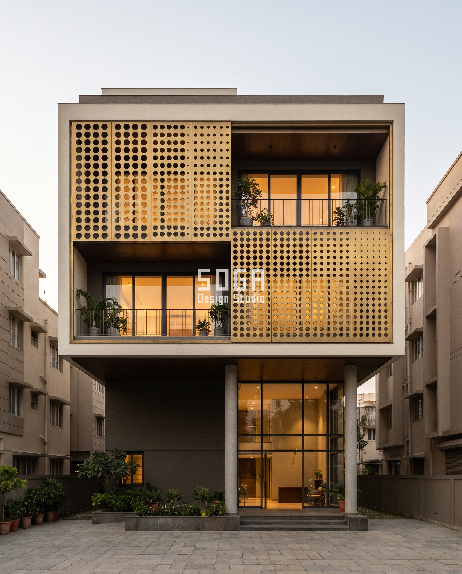
The Parametric Dissolve Veil in Kolkata’s Salt Lake Sector V grades its brass perforation from 8mm holes — the thickness of a pencil — at the dense end to 60mm holes, the width of a smartphone, at the dissolve corner. The cavity behind it grows with the holes: 40mm at the dense end, 150mm at the open corner. A 60mm hole only reads as shade, not as a view straight through to the wall, if the cavity behind it is deep enough to still throw a shadow at Kolkata’s low monsoon-season sun angle — and Kolkata’s high driving-rain exposure wants that depth regardless.
| Specification | Parametric Dissolve Veil |
|---|---|
| Module | 600mm x 600mm perforated brass cassette on a concealed carrier rail |
| What varies | Cavity depth 40mm to 150mm, tracking the 8mm-60mm hole gradient |
Parametric Facet Twist Tray
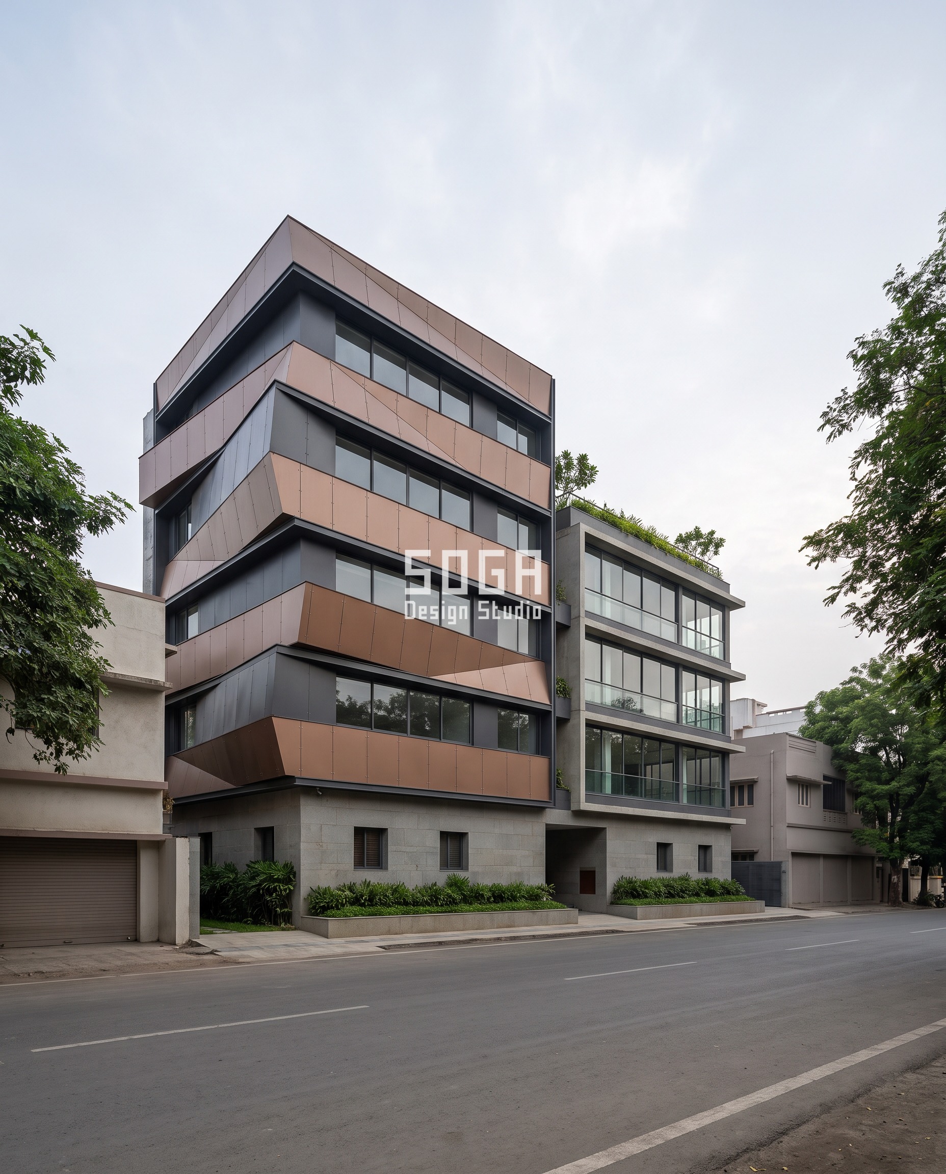
In Dharampeth, Nagpur, each floor of the Parametric Facet Twist Tray rotates 9 degrees further than the one beneath it, its corner projecting from 250mm — a kitchen shelf’s depth — at the base to 1700mm, deeper than a dining chair’s full seat, at the roofline. Up to the fourth floor that projection still rides a standard catalogue bracket inside the 40-300mm range. Past that, the corner’s own geometry forces the 1700mm reach onto a cantilevered steel outrigger beam, because a single bracket stretched that far would fail in bending long before the tray itself failed.
| Specification | Parametric Facet Twist Tray |
|---|---|
| Module | folded two-tone charcoal-and-copper aluminium tray, one floor-height module, steel outrigger above the 4th floor |
| What varies | Corner projection 250mm to 1700mm; bracket hands off to outrigger past 300mm |
Parametric Punched Screen Wall
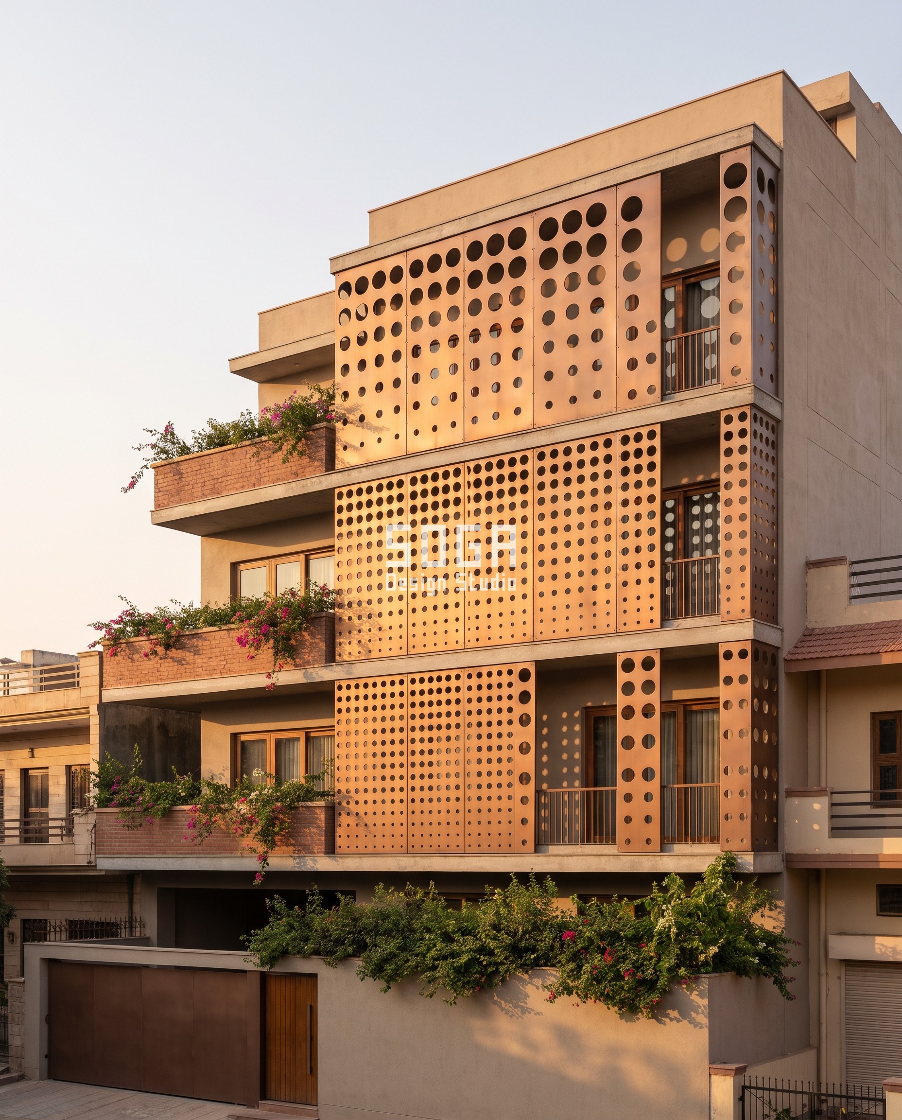
The Parametric Punched Screen Wall in Ratanada, Jodhpur grades its copper-bronze screen from 10mm holes, a rupee coin’s thickness, at the base to 75mm holes, a smartphone laid flat, at the top. Jodhpur’s low rainfall and high dust season mean the cavity behind the screen stays shallow — 40mm to 60mm, never pushed toward the deep end a coastal city would need — but it is never cut below 40mm either, because a narrower gap lets windborne dust bridge across it and seal the cavity shut within a season.
| Specification | Parametric Punched Screen Wall |
|---|---|
| Module | full-height anodised aluminium screen bay on a bolted steel sub-frame |
| What varies | Hole diameter 10mm to 75mm; cavity held at 40mm to 60mm, dust-floor enforced |
Parametric Fin Flip Frame
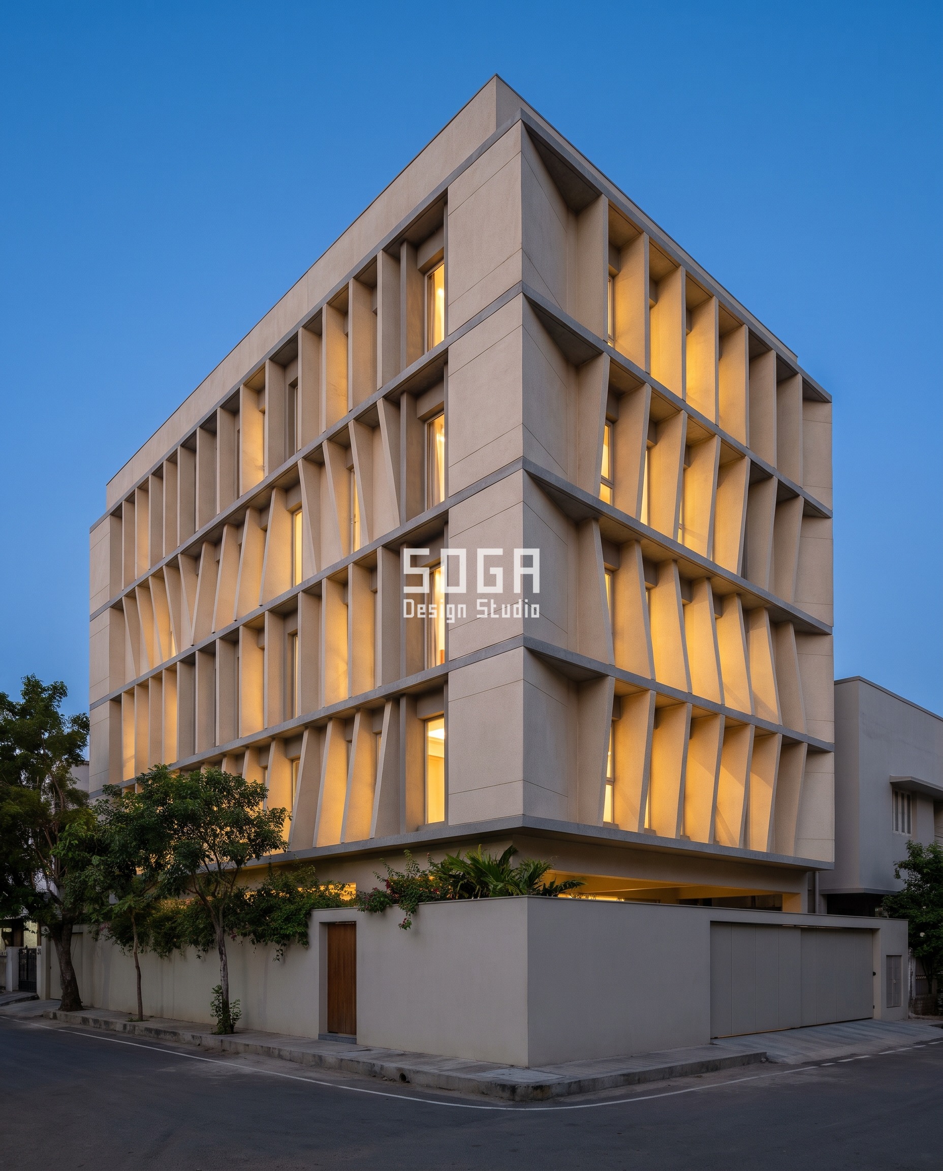
In R.S. Puram, Coimbatore, the Parametric Fin Flip Frame’s cream GFRC fins flip their angle floor by floor, projecting from 150mm — two bricks laid flat — at the shallowest bay to 1200mm, deeper than an adult’s forearm is long, at the deepest. Bays under 300mm sit on a standard catalogue bracket. Past that, the fin is carried on a stepped base-plate anchored to the slab edge rather than a longer single arm, because Coimbatore’s monsoon driving-rain exposure wants the deep end and the bracket’s own bending-moment limit won’t carry it there alone.
| Specification | Parametric Fin Flip Frame |
|---|---|
| Module | cream GFRC triangular fin cassette with hairline panel joints, one bay per module |
| What varies | Fin projection 150mm to 1200mm; base-plate takes over past 300mm |
Parametric Loop Swell Wall
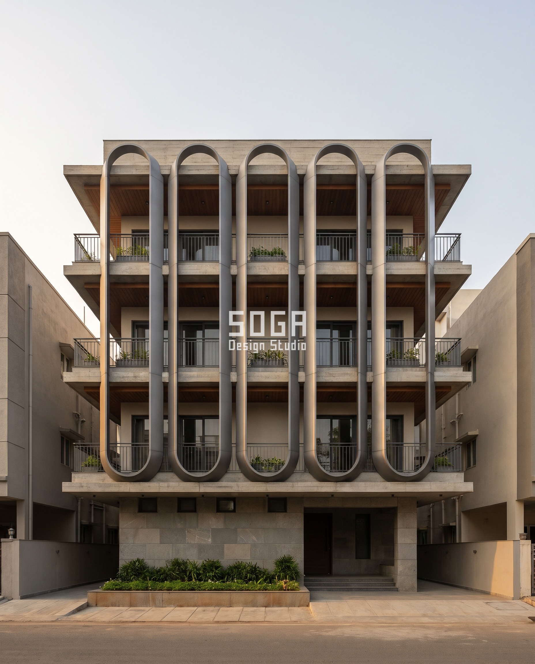
Five tall elliptical loops run the full facade height of the Parametric Loop Swell Wall in MVP Colony, Visakhapatnam, their graphite-grey aluminium thickness swelling from 150mm — a slim hardcover book — at the ends to 1100mm, deeper than a standard office desk, at mid-height. That swell lands deepest exactly where Visakhapatnam’s coastal driving-rain exposure wants the rain-shadow deepest, and the swollen base is carried clear of the structural wall on a stepped bracket rather than a single long arm once it passes the 300mm catalogue reach.
| Specification | Parametric Loop Swell Wall |
|---|---|
| Module | graphite-grey aluminium loop panel with hairline joints following the curvature, one loop per module |
| What varies | Loop wall thickness 150mm to 1100mm; stepped bracket past 300mm |
How The Cavity Is Actually Built
Every system above rides the same two-part fixing logic underneath its own numbers: a bracket that can step through the 40-300mm catalogue range in 20-30mm increments, and a hard floor below which the fixing changes rather than the cavity shrinking. The table below is the detail package that sits behind all five buildings, not a different spec for each.
| Design parameter | Specification |
|---|---|
| Primary bracket | Stainless-steel adjustable Z-bracket, 600mm vertical module, 40mm to 300mm reach in 20-30mm steps |
| Thermal isolation | EPDM thermal-break isolator pad at every bolt face, so the fixing never sits metal-on-metal against the RCC behind it |
| Past 300mm reach | Stepped base-plate bolted to the slab edge, or a cantilevered outrigger rail, in place of a longer single bracket arm |
| Base flashing | Continuous aluminium flashing with 10mm weep slots at 400mm centres |
| Drip edge | Projects at least 20mm clear of the plinth, throwing cavity runoff clear of the wall below it |
The Two Details That Decide Whether It Survives A Monsoon
- Stainless-steel adjustable Z-bracket on a 600mm vertical module, with an EPDM thermal-break isolator pad at every bolt face, covers the full 40-300mm catalogue range in its own steps; past 300mm the same module switches to a stepped base-plate bolted to the slab edge rather than a longer single arm.
- Continuous aluminium flashing at the base of every cavity, with 10mm weep slots at 400mm centres, draining onto a drip edge that projects at least 20mm clear of the plinth — so monsoon runoff carried down the cavity is thrown clear of the wall instead of tracking back down the plaster below it.
The Honest Limit
25mm to 40mm and 40mm to 300mm are a defensible starting band built from cross-checked manufacturer data, not a code. Nothing in NBC 2016, ECBC 2017 or Eco-Niwas Samhita 2018 prescribes a cavity figure, and no range in a blog post replaces one. Past 300mm, above roughly 15 storeys, or within 2km of open coastline, this band is a starting point for the project’s own wind-load and driving-rain calculation and the bracket manufacturer’s own pull-out test — not a substitute for either. We would rather say that plainly here than have a site engineer discover it the expensive way, after the scaffolding is already down.
What A Stand-Off Cavity Actually Costs
Buildability has a price tag, and most of it sits in the hardware nobody photographs.
| System / material | Indicative rate (per sq ft) |
|---|---|
| Ventilated cavity sub-frame & bracket hardware (25-300mm stand-off system) | ₹450-950 per sq ft, indicative, itemised per project |
| Perforated / folded metal facade skin (brass, aluminium or GFRC, varies by system) | ₹850-2,200 per sq ft, indicative, itemised per project |
| Flashing, weep detail and thermal-break isolators at the cavity base | ₹60-140 per sq ft, indicative, itemised per project |
What Happens When The Stand-Off Is Wrong In Either Direction?
Too shallow and the cavity cannot breathe: below roughly 25mm the stack-effect airflow that should dry the wall out after monsoon wetting stalls, and efflorescence and dark streak staining start showing within a few monsoon cycles — a failure mode every rainscreen source agrees on, even though none of them states the India number.
Too deep and the bracket fails instead: push a standard catalogue bracket’s reach past roughly 300mm and the bending moment at its base rises faster than its load capacity, which is why deep fins and trays get carried on a stepped base-plate or a secondary outrigger rail rather than a longer single bracket. We have not found a competitor page that states both failure modes in one place — most mention one and leave the other for someone else to discover.
Related Reading
- the 5 parametric facade systems SOGA builds across India
- how facade material changes the fixing detail
- how a bracket actually anchors into the RCC slab behind it
- how villas keep monsoon rain from tracking back into the wall
- the 6-9x spread rule behind every SOGA gradient
Frequently Asked Questions
What is the minimum air gap for a ventilated facade in India?
At least 25mm to 40mm, cross-checked from CWCT’s 25mm minimum, NHBC’s 38-50mm guidance and Cedral’s 30mm continuous cavity. Below 25mm the stack-effect airflow that dries the wall after monsoon wetting stalls, and efflorescence starts within a few monsoon cycles.
How deep should a facade fin stand off the wall before the bracket has to change?
Up to roughly 300mm on a standard catalogue bracket, stepped in 20-30mm increments. Past that, the bending moment at the bracket’s base overtakes its bolt’s pull-out and fatigue capacity, so the fixing switches to a stepped base-plate or a cantilevered outrigger rail instead.
Does the stand-off distance change by city or climate zone in India?
Yes. Coastal and eastern cities like Kolkata, Coimbatore and Visakhapatnam need 150mm to 300mm of rain-shadow depth, while a dry, dust-heavy city like Jodhpur holds the cavity at a shallower 40mm to 60mm and never below a 40mm dust-sealing floor.
What does a facade stand-off and bracket system cost in India?
Sub-frame and bracket hardware for a 25-300mm stand-off system runs roughly ₹450 to ₹950 per sq ft, indicative and itemised per project, which is typically 30-60% of the facade’s total installed cost.
Does NBC, ECBC or Eco-Niwas Samhita specify a stand-off distance for facades?
No. NBC 2016, ECBC 2017 and Eco-Niwas Samhita 2018 all set thermal and SHGC performance targets, not a cavity dimension, which is why SOGA states its own cross-checked 25-40mm and 40-300mm ranges rather than citing a code figure that does not exist.
Get Your Facade’s Stand-Off Calculated
SOGA Design Studio sizes this cavity project by project, against the actual city’s monsoon exposure, dust season and bracket spec, never copied from the last job. Share your plot, city and facade brief and we will come back with a defensible stand-off range built for that building specifically.