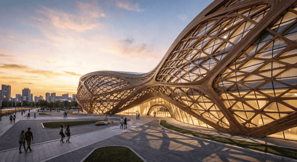
There is no correct size for a facade module. There is only a correct size for a distance. A ceramic shingle 300 mm across reads as a distinct object on a three-storey house seen from sixteen metres; the same shingle on a twenty-three-storey tower seen from a hundred and forty metres is not a shingle at all, it is a grey wash with a faint grain in it. Nothing about the part changed. The viewer moved back. That is the whole of it, and it is why facade module size is set by building height and street width rather than by the fabricator’s sheet or by anyone’s taste. This page runs one question through six SOGA concepts in Singapore and Dubai, from three storeys to twenty-three, and leaves you with the arithmetic to size your own building.
Half a Degree, and the Two Numbers That Set Everything Above It
Work it from the eye rather than from the elevation. A module is legible as a discrete object when it takes up enough of your field of view to be resolved as a shape while you are walking or driving past it, in the low contrast a facade actually has on an overcast morning. Our working floor for that is half a degree. Below half a degree the module does not vanish – you can still see that the wall is not smooth – but it stops being read as a thing with a shape and starts being read as texture.
Half a degree converts into a rule you can do in your head on site: the module in millimetres has to be at least nine times the viewing distance in metres. At sixteen metres that is 144 mm. At forty metres, 360 mm. At ninety metres, 810 mm. At a hundred and forty metres, 1,260 mm. Those four numbers are the floor under the six buildings on this page, and every one of them clears it.
The floor is not the target. A module sitting exactly on the floor reads as a shape and nothing more: it carries no conviction, and it is the first thing to disappear in haze, in rain and against a bright sky. We size for roughly one to two and a half degrees, which is twenty to forty-five times the viewing distance in metres. At sixteen metres that is a 320 to 720 mm module. At a hundred and forty metres it is 2,800 to 6,300 mm – which is why the tallest building here carries blades a full storey tall and only fourteen of them to a floor.
Then the second and harder rule, the one that decides whether parametric variation was worth paying for. Variation is a second module: the difference between one part and its neighbour. It obeys the same optics. On the Bukit Timah house the shingle grows about 12 mm from one course to the next; at sixteen metres that is four hundredths of a degree and nobody on earth sees it. What is seen is the accumulation – 100 mm across the full course, 0.36 degrees, which reads as a gradient. So a parametric move has to be designed twice: once as a per-part step a fabricator can hold, and once as an accumulated change across the visible run that clears about one degree. If the accumulation does not clear one degree, the variation has been paid for and not delivered. That is the same discipline as the rest of our parametric facade design work – the variation is a tool setting rather than a set of unique parts, and it has to be visible from where people actually stand.
Height, Street Width and the Distance the Viewer Actually Stands
The design viewing distance is the larger of two numbers, and you can get both off a site plan before anyone opens a modelling package. The first is the street: kerb-to-kerb width plus both setbacks, which is where a pedestrian on the far side physically stands. The second is the height: to take in a whole building without craning your neck you need to be roughly one and a half to two times its height away from it. On a villa the street wins. On a tower the height wins, and it wins by a wide margin.
That is why the second building on this page – a two-storey villa in Al Barsha – carries a module five times larger than the three-storey house in Bukit Timah. The villa is shorter and its module is bigger, because an Al Barsha villa road is 12 m kerb to kerb with a 3 m boundary setback and a 7 m front garden, and it is read at 40 kph from a car, while the Bukit Timah lane is 7.2 m wide under a closed tree canopy and is read on foot. Height did not set that module. Street width did.
| Height band | Design viewing distance | Module floor (half a degree) | Module size we design to | Modules per 10 m of elevation width |
|---|---|---|---|---|
| 2 to 3 storeys (7 to 11 m) | 14 to 22 m | 130 to 200 mm | 280 to 700 mm | 14 to 36 |
| 4 to 6 storeys (13 to 20 m) | 25 to 45 m | 225 to 405 mm | 550 to 1,400 mm | 7 to 18 |
| 7 to 10 storeys (22 to 33 m) | 35 to 60 m | 315 to 540 mm | 800 to 1,800 mm | 6 to 13 |
| 11 to 18 storeys (35 to 60 m) | 55 to 100 m | 495 to 900 mm | 1,200 to 2,600 mm | 4 to 8 |
| 19 to 25 storeys (62 to 82 m) | 90 to 150 m | 810 to 1,350 mm | 1,900 to 4,000 mm | 2 to 5 |
| 26 storeys and above | 140 m and beyond | 1,260 mm and up | 3,000 mm and up | 3 and fewer |
The last column is deliberately not modules per floor. Count per floor is a useless number to compare across buildings, because a G+18 tower is four times the elevation width of a house and will always carry more parts on a floor whatever the module. Normalised per ten metres of elevation width, the trend is clean and it runs one way: 33 modules per 10 m on the three-storey house, 3.4 per 10 m on the twenty-three-storey tower. Ten to one, over seven times the height.
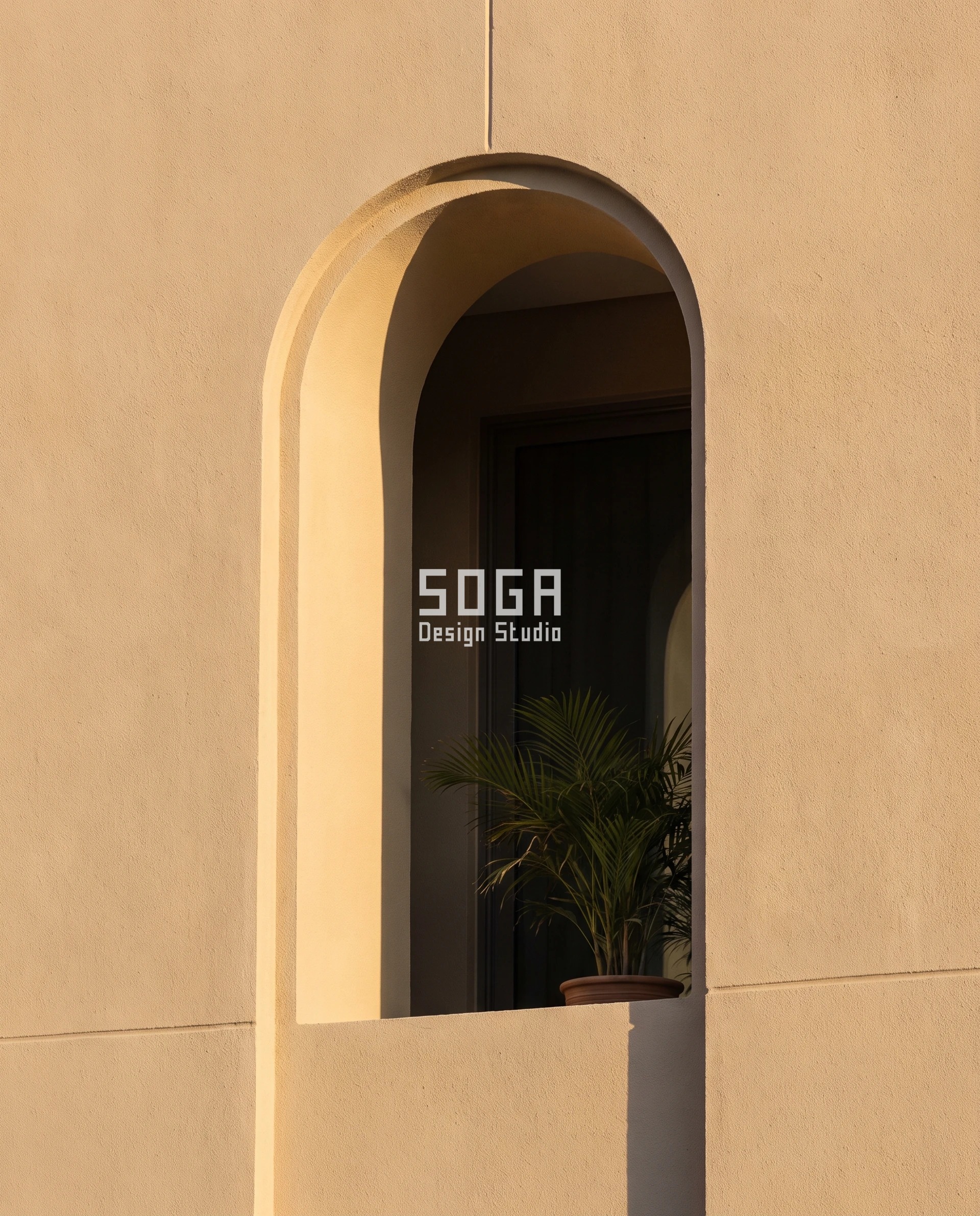
The macro above is the same Al Barsha arch as the elevation shot, read from three metres instead of twenty-two. At three metres the 520 mm reveal subtends nearly ten degrees and the arch is practically a room; at twenty-two metres the same reveal is 1.35 degrees, about the width of your thumbnail at arm’s length. That collapse is what makes detail drawings misleading. A 1:5 detail is drawn at a viewing distance nobody will ever use.
Two positions, not one, once you pass ten storeys
Above roughly ten storeys a building stops having a single viewing distance. The base is read from the pavement opposite and the crown is read from the next junction, the park across the road, or the far side of the water – and those two positions can be eighty or a hundred metres apart. That is not a nuisance. It is a design instrument, and two of the buildings here use it directly. The Tiong Bahru fin rank steps its projection 60 mm per floor precisely so the shadow it casts holds the same angular size on every floor even though the floors are read from distances 33 m apart. The Paya Lebar tower accepts that its upper third will be read from 140 m and designs a second, tonal register for it. Choosing one viewing distance for a tall building means choosing which half of it works.
1. Singapore Parametric Scale Course: A 3-storey Private House
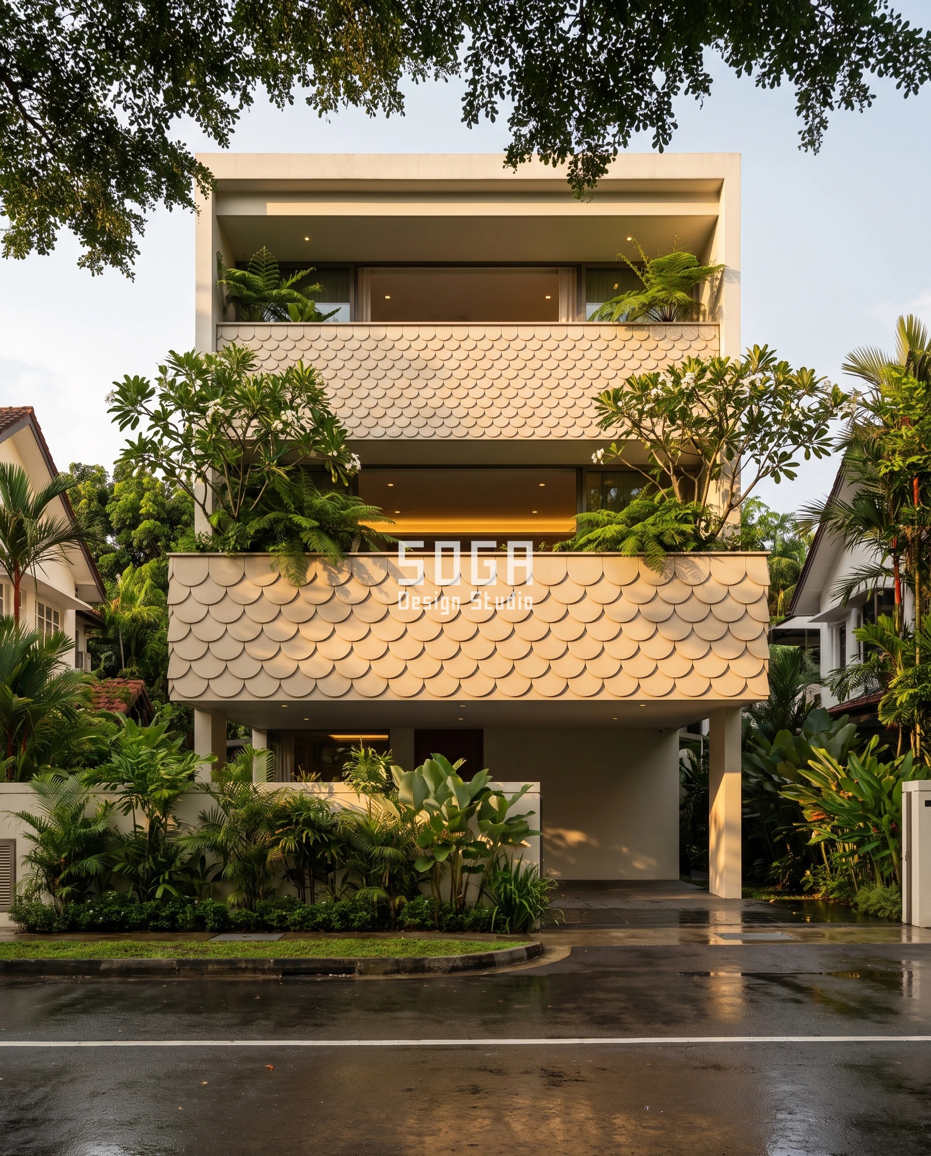
Design seed: Narrow leafy plot, calm off-white RCC frame with dead-straight floor lines x two continuous balcony bands carrying the only decorated surface on the house x a single lapped ceramic shingle repeated at an unvarying 300 mm pitch x one stepping variable in the shingle’s width x a sixteen-metre viewing distance across a narrow road, which is the number that fixed the shingle at 300 mm and nothing larger. This 3-storey private house in Bukit Timah, Singapore wears a Parametric Scale Course skin in sand-cream through-body glazed ceramic shingles, 8 mm, hooked on a stainless clip rail over a drained and back-ventilated 40 mm cavity; off-white through-coloured render to the body; dark timber-shade window frames; honed grey granite plinth to 900 mm. Tropical at one degree north, 2,340 mm of rain a year and a monsoon that arrives sideways. The shingle lap is the rain control: every course oversails the one below by 60 mm, so water is thrown clear of the joint rather than held in it, and the 40 mm back-ventilated cavity dries the wall between showers. Glazed ceramic was chosen over metal because at a 16 m viewing distance under a closed tree canopy the surface is read in reflected green light, and a glaze holds its colour in that light where a coated metal goes flat. The parametric variation is written into the fabrication drawings, not sprayed on afterwards.
How the Parametric Scale Course is built
| Design parameter | Specification |
|---|---|
| Module and count | 300 mm average shingle on a 220 mm course rise, 36 shingles to every floor course across a 10.8 m street elevation – 33 modules per 10 m of elevation width, the densest skin on this page. 108 shingles on the street face in total. Each shingle weighs 1.9 kg: a one-hand lift off a light scaffold, no mechanical plant on a residential lane. |
| The one variable: shingle width | Only the width changes. 280 mm at the bottom of the lower band, opening 12 mm per course to 380 mm at the top of the upper band. Nine discrete widths off one press tool with nine drop-in inserts. The pitch of the clip rail, the course rise, the lap, the colour and the fixing are identical on every course and every floor. |
| Design viewing distance | 16 m. The lane is a 7.2 m carriageway with a 3 m verge and a 5.5 m front setback, and the house is 11 m tall, so a pedestrian on the far verge has the whole elevation in view without stepping back. There is no second, longer viewing position – the road bends and the canopy closes. One distance, one module size. |
| Angular size at that distance | 280 mm reads at 1.00 degrees, 380 mm at 1.36 degrees. The half-degree legibility floor at 16 m is 144 mm, so the shingle sits at roughly twice the floor and holds its shape in rain and under the tree canopy. The 12 mm step between neighbouring courses is 0.04 degrees and is invisible on its own; the 100 mm accumulated across the full course is 0.36 degrees and reads as a gradient. |
| Substructure and fixing | Stainless clip rail at 220 mm centres on a 40 mm top-hat carrier, thermally broken at every bracket, over 50 mm mineral wool and a fully drained and back-ventilated cavity. Two concealed clips per shingle, no visible fixing. Open-jointed lap: driving rain runs down the cavity face and out at a continuous flashing above the plinth. |
| Tool count and unique parts | One tool. Nine width inserts. Zero unique parts – a 380 mm shingle and a 280 mm shingle are the same drawing with a different insert number. The variation is a tool setting, which is why the graded course costs the same to make as a flat one. |
Material & colour: hero skin in Sand-cream glazed ceramic / off-white render body / timber-shade frames / grey granite plinth, kept to a restrained palette so the geometry does the talking. Indicative facade cost: SGD 105 – SGD 165 per sq ft of elevation, all-in – shingles, clip rail, carrier, insulation, cavity and flashings. The band is wide because 340 sq m is a small area to mobilise: the tool and the scaffold are the same whether you buy 340 sq m or 3,400, fully designed and installed, with an itemised estimate produced per project.
2. Dubai Parametric Arch Reveal: A 2-storey Villa
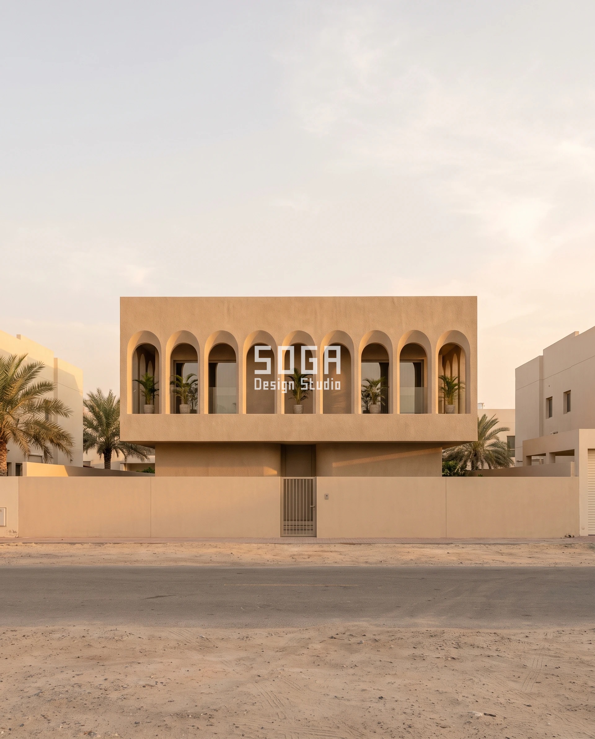
Design seed: Wide low villa plot on a 12 m road, calm off-white RCC frame x one continuous solid band at first-floor level carrying the whole gesture x a single pill-arch aperture cut nine times into that band at an unvarying 1,750 mm bay x one stepping variable in the arch’s clear width x a 520 mm reveal depth, because on this building the shadow is the module and the opening is only the thing that makes it. This 2-storey villa in Al Barsha, Dubai wears a Parametric Arch Reveal skin in hand-floated sand-tone lime-cement plaster, 22 mm in three coats over blockwork, integral colour, arris rounded to a 25 mm radius at every reveal; recessed dark bronze-tone metal window frames set 520 mm back; dark basalt paving and a matching plinth. Hot desert at 25 degrees north, 45 plus in July and a low western sun that arrives almost horizontally in the hour before sunset. The 520 mm reveal is the shading device: it holds the recessed glazing in full shadow until the sun is within 24 degrees of the horizon, which on a west elevation is the last forty minutes of the day. Massive plastered blockwork was chosen over a hung skin because on a low villa the thermal mass is doing real work – the band lags the afternoon peak by five to six hours and gives it back after midnight. The parametric variation is written into the fabrication drawings, not sprayed on afterwards.
How the Parametric Arch Reveal is built
| Design parameter | Specification |
|---|---|
| Module and count | Nine pill-arch apertures on a 15.6 m first-floor band, one per 1,750 mm structural bay, arranged symmetrically about the centre. Six modules per 10 m of elevation width – a fifth of the density of the Bukit Timah house, on a building that is one storey shorter. Bay pitch, arch spring height and arch crown radius are identical in all nine. |
| The one variable: arch clear width | 900 mm at the two outer bays, stepping 200 mm per bay inward – 900, 1,100, 1,300, 1,500, 1,700, 1,500, 1,300, 1,100, 900. Five formers used twice each. Nothing else changes: not the bay, not the spring line, not the 520 mm reveal depth, not the plaster. |
| Design viewing distance | 22 m, and this is the number that makes the villa look wrong on a list sorted by storey count. The road is 12 m kerb to kerb, the boundary wall sits 3 m back and the villa sits 7 m behind that. A two-storey villa on an Al Barsha road is seen from further away than a three-storey house on a Bukit Timah lane, and it is also seen at 40 kph from a car. Height did not set this module. Street width did. |
| Angular size at that distance | The opening is generous – 900 mm reads at 2.34 degrees and 1,700 mm at 4.43 degrees – but the opening is not what carries the design. The 520 mm reveal throws a shadow block 520 mm wide down one cheek of every arch, and that shadow reads at 1.35 degrees, right in the band we design to. Cut the reveal to 150 mm and the arch flattens to a shape painted on a wall at 0.39 degrees, below the floor, whatever the opening measures. |
| Substructure and fixing | There is none, and that is the point of choosing a carved band rather than a hung one on a two-storey villa. The band is 250 mm blockwork on the slab edge, arches turned on five reusable GRP formers, rendered monolithically. No carrier, no cavity, no clip, no thermal bridge to break. The reveal cheeks are rendered with a 1:60 outward fall so wind-blown dust washes off in the two or three rain events a year rather than banking on a flat ledge. |
| Tool count and unique parts | Five formers for nine arches. Zero unique parts. The formers are struck, cleaned and reused on the rear elevation, so the same five pieces of GRP make eighteen arches. |
Material & colour: hero skin in Warm sand plaster / dark bronze-tone recessed frames / basalt plinth and paving, kept to a restrained palette so the geometry does the talking. Indicative facade cost: AED 85 – AED 140 per sq ft of elevation, all-in – blockwork, formers, three-coat render, reveal detailing and the recessed frame line. The cheapest system on this page per square foot and the most labour-intensive per square metre, because everything is site-formed, fully designed and installed, with an itemised estimate produced per project.
3. Dubai Parametric Crease Rank: A G+5 Apartment Building
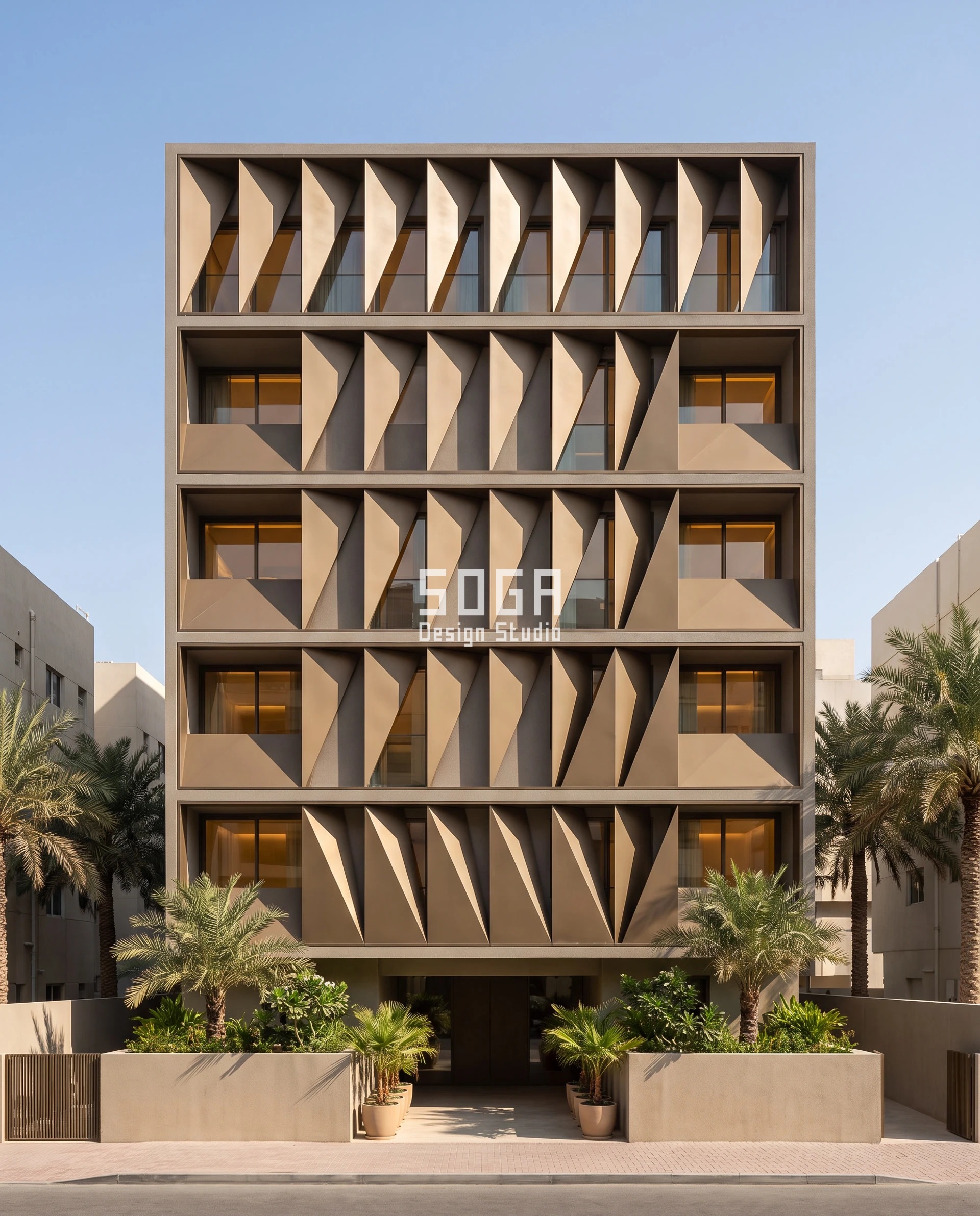
Design seed: Mid-block apartment plot on a side street off Al Wasl Road, calm off-white RCC frame with straight slab lines x one continuous balcony band per floor x a single folded triangular metal plate repeated at an unvarying 1,150 mm pitch on every band x one stepping variable in the fold angle x a 40 m viewing distance from the far pavement, which is why the plate is four times the width of the Bukit Timah shingle. This G+5 apartment building in Al Wasl, Dubai wears a Parametric Crease Rank skin in 3.0 mm 5052-H32 coil-coated metal plate in a bronze-tone PVDF finish, folded to a shallow triangular tray with a 25 mm returned edge on all four sides, hooked onto a T-rail; off-white through-coloured render to the piers; clear low-E glazing set back 300 mm. Hot desert, and the fold is doing two jobs. The 37-degree crease at the top of the building self-shades the balcony line through the middle of the day when the sun is high, while the 12-degree crease at ground stays nearly flat because the podium is already shaded by the buildings opposite. The open 12 mm joints and the 100 mm drained cavity let the plate run 20 to 25 degrees hotter than the wall behind it without transferring that heat, and the cavity vents at every slab edge so the stack does not build. The parametric variation is written into the fabrication drawings, not sprayed on afterwards.
How the Parametric Crease Rank is built
| Design parameter | Specification |
|---|---|
| Module and count | 1,150 mm wide by 1,050 mm high folded plate, 16 plates to a floor across an 18.4 m elevation – 8.7 modules per 10 m of elevation width. 96 plates over six floors. Each plate weighs 11.4 kg and hooks on with two hands off a mast climber. |
| The one variable: fold angle | The plate is creased on one vertical line, off-centre at 430 mm. Only the included angle of that crease changes: 12 degrees at ground, opening 5 degrees per floor to 37 degrees at level five. Six settings on one press brake programme. The blank is the same rectangle every time – same coil width, same nest, same 25 mm return. |
| Design viewing distance | 40 m. The side street is 14 m, the far pavement is at 17 m and the building is 19.8 m tall, so the position from which the whole elevation is in view is the far side of the junction at 40 m. That is the distance the plate is sized against, not the 17 m at which you walk past it. |
| Angular size at that distance | The 1,150 mm plate reads at 1.65 degrees – comfortably above the 360 mm floor at 40 m. The fold itself is the harder number: at 12 degrees the crease projects 120 mm and reads at 0.17 degrees, below the floor and effectively flat; at 37 degrees it projects 385 mm and reads at 0.55 degrees, just clear. That is the whole reason the angle opens as it rises. The lower floors are seen from the pavement at 17 m, where 120 mm is 0.40 degrees and adequate; the upper floors are only ever seen from 40 m. |
| Substructure and fixing | Extruded T-rail at 1,150 mm centres on stainless helping-hand brackets fixed to cast-in channel at each slab edge, 100 mm drained cavity, open joints of 12 mm on all four sides of every plate. Two hooks and one restraint screw per plate. No sealant anywhere in the field of the elevation. |
| Tool count and unique parts | One press brake programme, six stored angle settings, one blank. Zero unique parts across 96 plates. A 37-degree plate and a 12-degree plate carry the same part number and differ by a line on the setting sheet. |
Material & colour: hero skin in Bronze-tone PVDF metal plate / off-white render piers / dark bronze frames, kept to a restrained palette so the geometry does the talking. Indicative facade cost: AED 150 – AED 235 per sq ft of elevation, all-in – plate, T-rail, brackets, cavity, cavity barriers and the glazing line behind. The six fold angles add nothing: the cost is in the coil, the coating batch and the bracket count, fully designed and installed, with an itemised estimate produced per project.
4. Singapore Parametric Fin Depth Rank: A G+6 Boutique Condominium
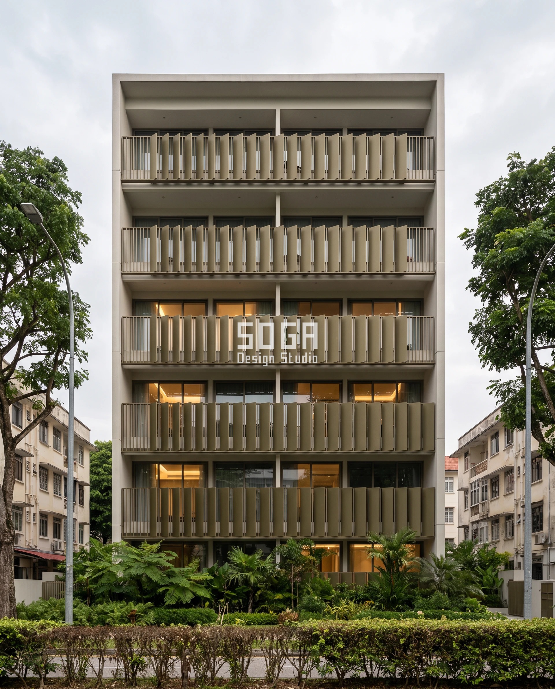
Design seed: Infill plot between two older walk-up blocks, calm off-white RCC frame x a fully glazed body with one continuous vertical fin rank standing 300 mm clear of the glass x a single extruded metal fin repeated at an unvarying 1,050 mm pitch x one stepping variable in how far the fin stands out x a building whose base is read from 12 m and whose top is read from 45 m, so the fin has to grow to keep the same shadow. This G+6 boutique condominium in Tiong Bahru, Singapore wears a Parametric Fin Depth Rank skin in olive-bronze anodised 6063-T6 extruded metal fin, 220 x 60 mm hollow section in 3,150 mm storey-height lengths, on stainless cantilever arms fixed to cast-in channel at every slab edge; unitised low-E glazing behind; off-white board-marked concrete to the flanks. Tropical, and on a north-south street the fins are working against the low east and west sun rather than the overhead sun. Vertical fins were chosen for that reason: a horizontal blade does nothing at 8 am on an east elevation one degree from the equator. Effective screen porosity to the low sun closes from 83 per cent at ground to 49 per cent at level six as the projection grows, which also happens to be where the shading is most needed because the lower floors are shaded by the walk-ups opposite. No fin face points upward, so there is no ledge for the monsoon to sit on. The parametric variation is written into the fabrication drawings, not sprayed on afterwards.
How the Parametric Fin Depth Rank is built
| Design parameter | Specification |
|---|---|
| Module and count | 220 x 60 mm fin in 3,150 mm storey-height lengths at a fixed 1,050 mm pitch, 28 fins to a floor across a 29.4 m elevation – 9.5 modules per 10 m of elevation width. 196 fins over seven floors. Each fin is 7.1 kg: two people, no crane, off a mast climber. |
| The one variable: fin projection | Only how far the fin stands out from the glass line changes. 180 mm at ground, stepping 60 mm per floor – 180, 240, 300, 360, 420, 480, 540 – set by which of seven stainless cantilever arms takes the fin. One extrusion die, one anodising batch, one length. Seven arms, seven part numbers, and the arm is a bracket, not a facade part. |
| Design viewing distance | There are seven of them, and that is the whole design. The street is 12 m, so the ground floor is read at 12 m from the opposite pavement. Each floor above is read from progressively further out, because you have to step back to see it over the block opposite – roughly 5.5 m further per floor, reaching 45 m for level six from the junction at the end of the road. |
| Angular size at that distance | This is the number to check. The fin’s own 60 mm face is invisible at any of these distances. What reads is the shadow slot the projection cuts on the glass. Ground: 180 mm at 12 m is 0.86 degrees. Level three: 360 mm at 28.5 m is 0.72 degrees. Level six: 540 mm at 45 m is 0.69 degrees. Every floor lands between 0.69 and 0.86 degrees. Hold the projection at 180 mm all the way up and level six falls to 0.23 degrees – less than half the legibility floor, and the top three storeys read as plain glass. |
| Substructure and fixing | Stainless cantilever arms at 1,050 mm centres, two per fin per storey, bolted to cast-in channel at the slab edge with a 12 mm thermal break washer. Fin ends closed with a bonded cap so nesting birds and monsoon water have nowhere to go. Every fin is demountable from a mast climber for facade cleaning access, which we fix before the fin pitch. |
| Tool count and unique parts | One die. One anodising batch – all 196 fins are a single colour lot, which is what stops an anodised elevation going patchy. Zero unique fins. Seven bracket arms, which are hidden, galvanised and cheap. |
Material & colour: hero skin in Olive-bronze anodised metal fins / off-white board-marked concrete flanks / clear glazing, kept to a restrained palette so the geometry does the talking. Indicative facade cost: SGD 130 – SGD 205 per sq ft of elevation, all-in – fins, cantilever arms, thermal breaks and the unitised glazing line behind. Anodising sits at the top of the band because a single colour lot for 196 fins means one tank booking and no second chances, fully designed and installed, with an itemised estimate produced per project.
5. Singapore Parametric Blade Tilt Rank: A G+18 Residential Tower
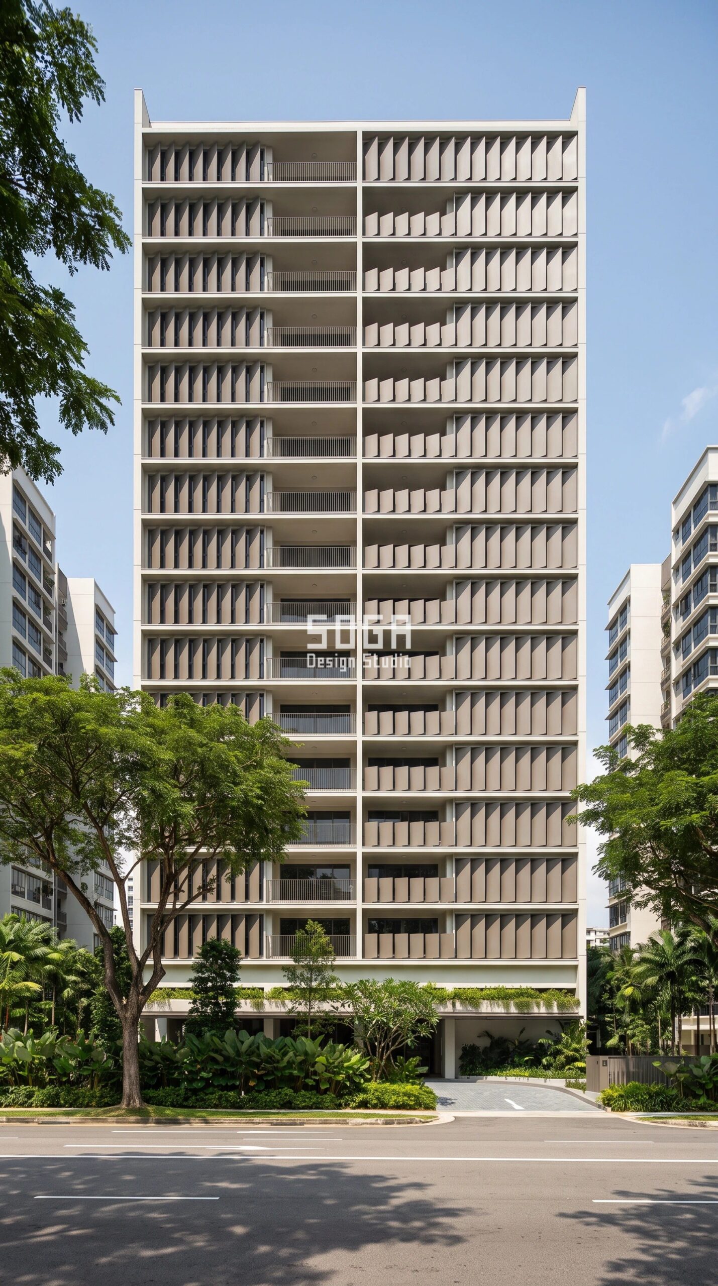
Design seed: Corner plot on a 40 m arterial, calm off-white RCC frame with dead-straight slab lines x one continuous balcony band per floor x a single flat metal blade shingle repeated at an unvarying 1,440 mm pitch x one stepping variable in how far the blade is turned about its own vertical axis x a tower tall enough that the base and the crown are read from two completely different distances, so the same blade has to work twice. This G+18 residential tower in Paya Lebar, Singapore wears a Parametric Blade Tilt Rank skin in 2.5 mm 5005-H14 coil-coated metal blade in a warm-grey PVDF finish, 1,440 x 1,180 mm with a 30 mm returned edge, pinned top and bottom on a stainless pivot pin at a fixed setting; off-white through-coloured render to the cores; clear low-E glazing set back 450 mm. Tropical, on an arterial that runs close to east-west, so the long elevations face north and south and the hard work is the low morning and evening sun on the flanks. The tilt is set to close the screen progressively toward the top, where there is no self-shading from neighbouring blocks: effective porosity to the low sun runs from 100 per cent at ground to 41 per cent at level eighteen. Blades are pinned vertically edge-out, so 2,340 mm of annual rain runs off the blade face and no horizontal surface collects standing water at height. The parametric variation is written into the fabrication drawings, not sprayed on afterwards.
How the Parametric Blade Tilt Rank is built
| Design parameter | Specification |
|---|---|
| Module and count | 1,440 x 1,180 mm flat blade at a fixed 1,440 mm pitch, 32 blades to a floor across a 46 m elevation – 7.0 modules per 10 m of elevation width. 608 blades over nineteen floors. Each blade is 14.8 kg and is pinned, not bolted: it goes up on a monorail hoist, two per lift. |
| The one variable: blade tilt | Only the angle of the blade about its own vertical pivot changes. 0 degrees at ground, stepping 3 degrees per floor to 54 degrees at level eighteen. Nineteen pivot settings, one for each floor, set by a machined flat on the pin. The pitch, the blade size, the pivot position, the colour and the fixing are identical on all 608. |
| Design viewing distance | Two, not one, and they are 85 m apart. The lower eight floors are read from the far pavement of the 40 m arterial at 55 to 65 m. The upper eleven floors cannot be seen from there at all without craning, and are read from the park across the junction at 110 to 140 m. A tower is not one elevation; it is a near elevation stacked on top of a far one. |
| Angular size at that distance | Near register: 1,440 mm at 55 m is 1.50 degrees – the blade is unambiguously an object and the tilt on each floor is readable as a turn. Far register: 1,440 mm at 140 m is 0.59 degrees, only just clear of the half-degree floor, and the apparent width of a blade turned 54 degrees drops to 846 mm, or 0.35 degrees. Above roughly level twelve the individual blade stops being an object. What survives is tone – the face turning from full-on light to edge-on shadow across the upper third. That is a deliberate second register, not a failure, but it is the point at which a 1,440 mm module has run out of room. |
| Substructure and fixing | Stainless pivot pin top and bottom into a bracket on the balcony upstand and the soffit above, with the tilt fixed at manufacture and a tamper-proof collar. No moving parts, no motors, no maintenance regime. Blades are removable individually from a building maintenance unit cradle – we ran the cradle reach and the tie-off spacing before the blade pitch was fixed. |
| Tool count and unique parts | One blank, one folding programme, one coating batch. Zero unique blades. The nineteen tilts live in the pin, which is a 40 mm turned stainless part, and the setting sheet is one page. |
Material & colour: hero skin in Warm-grey PVDF metal blades / off-white render cores / dark grey frames, kept to a restrained palette so the geometry does the talking. Indicative facade cost: SGD 145 – SGD 225 per sq ft of elevation, all-in – blades, pivot brackets, upstand reinforcement and the glazing line behind. Height is what moves the band: at nineteen floors the hoist, the cradle and the tie-offs cost more than the blade does, fully designed and installed, with an itemised estimate produced per project.
6. Dubai Parametric Blade Width Rank: A G+22 Residential Tower
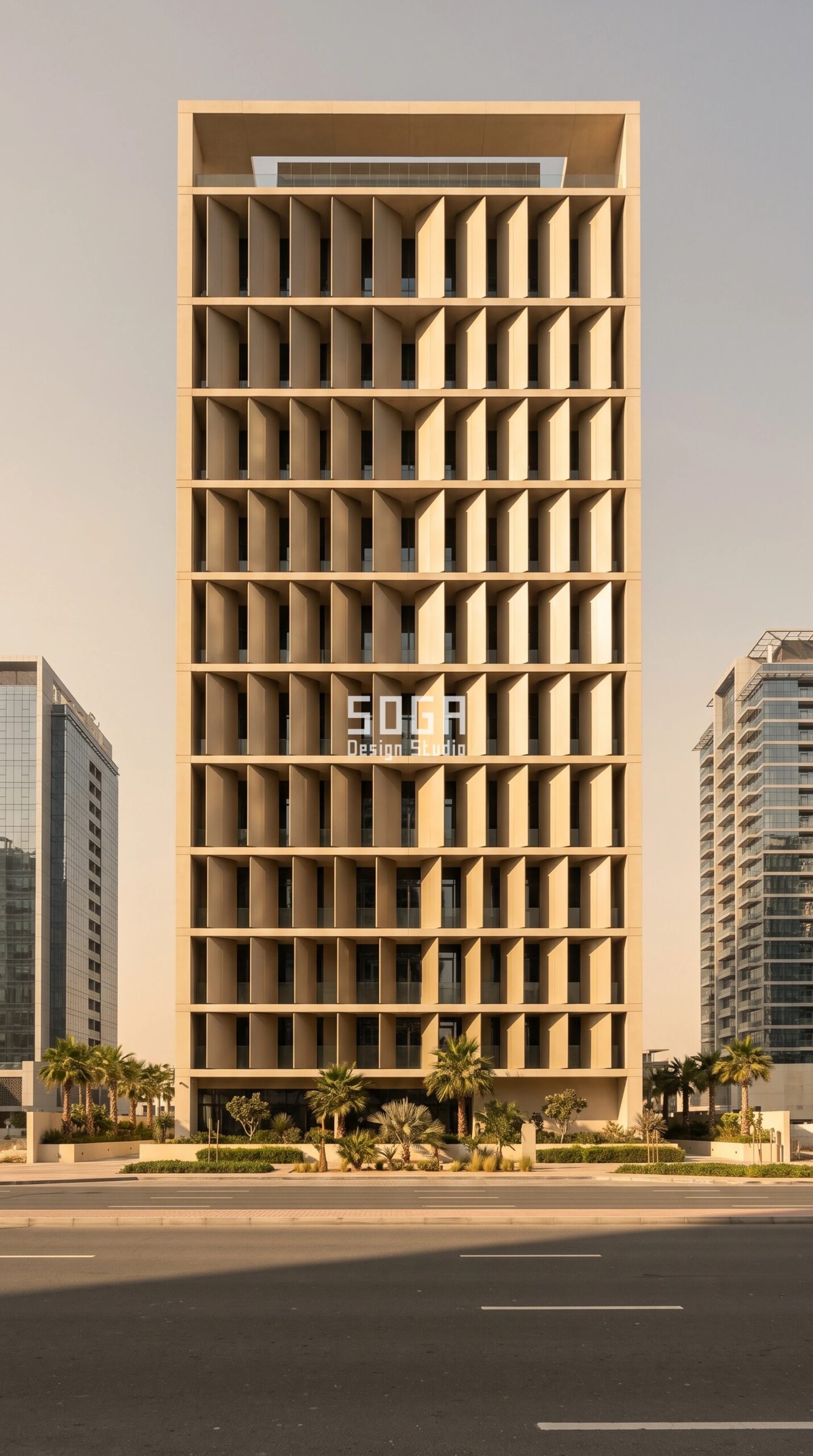
Design seed: Waterside tower plot on a 34 m boulevard, calm off-white RCC frame x one upright shaped blade per bay standing a full storey tall in front of the balcony line x a single blade profile repeated at an unvarying 2,900 mm bay on every one of twenty-three floors x one stepping variable in the blade’s width x a 140 m viewing distance, at which the blade is the smallest thing on the building that anybody can actually see. This G+22 residential tower in Business Bay, Dubai wears a Parametric Blade Width Rank skin in 2.5 mm 5052-H32 coil-coated metal in a champagne-tone PVDF finish, roll-formed to a shallow shaped upright 3,100 mm tall with a 45 mm returned edge, on a stainless spigot top and bottom; off-white through-coloured render to the core walls; grey low-E glazing set back 600 mm behind the blade line. Hot desert with a hard low western sun off the water and salt-laden humidity for eight months of the year. The closing gap is the shading strategy: the lower floors are shaded by the towers opposite for most of the afternoon and can afford 45 per cent porosity, while the upper floors see the sun to the horizon and are closed to 7 per cent. The 600 mm zone behind the blade is ventilated top and bottom at every floor, so the blade runs hot and the balcony behind it does not. PVDF over 5052-H32 was specified for the marine exposure. The parametric variation is written into the fabrication drawings, not sprayed on afterwards.
How the Parametric Blade Width Rank is built
| Design parameter | Specification |
|---|---|
| Module and count | One storey-tall blade per 2,900 mm bay, 14 blades to a floor across a 40.6 m elevation – 3.4 modules per 10 m of elevation width. That is one tenth the density of the Bukit Timah house, on a building seven times its height. 322 blades over twenty-three floors. Each blade is 3,100 mm tall, up to 2,700 mm wide and 62 kg: a crane pick or a monorail lift, never a hand lift. |
| The one variable: blade width | The bay never moves. Only the blade inside it gets wider – 1,600 mm at ground, stepping 50 mm per floor to 2,700 mm at level twenty-two – so the gap between neighbouring blades closes from 1,300 mm to 200 mm and screen porosity falls from 45 per cent to 7 per cent. Twenty-three width settings on one roll-form line. Same profile, same height, same spigot, same colour. |
| Design viewing distance | 140 m, and it is the boulevard that sets it rather than the tower. The road is 34 m, the landscaped setback is 18 m, and the first position from which all twenty-three floors are in view without craning is the far side of the water at roughly 140 m. Anything sized for the 52 m kerbside view is sized for a view almost nobody uses. |
| Angular size at that distance | 1,600 mm reads at 0.65 degrees and 2,700 mm at 1.10 degrees; the 3,100 mm blade height reads at 1.27 degrees. All clear of the 1,260 mm floor that 140 m imposes. But the 50 mm per-floor step is 0.02 degrees and the full 1,100 mm accumulation is 0.45 degrees – both below the floor. Nobody will ever see the blade get wider. What they see is the gap closing: 1,300 mm at 0.53 degrees reads as an open slot, 200 mm at 0.08 degrees reads as solid metal. Above twenty storeys you stop designing a dimension and start designing a tone. |
| Substructure and fixing | Stainless spigot into a cast-in socket on the balcony upstand and a sliding restraint at the soffit above to take slab deflection and inter-storey drift. Blade acts as a fall-restraint element in front of a 1,100 mm structural balustrade, never instead of one. Cavity behind the blade line is 600 mm – a working access zone, not a rainscreen cavity, and it is that access study that fixed the bay at 2,900 mm. |
| Tool count and unique parts | One roll-form line. One folding programme. One coating colour across all 322 blades. Zero unique profiles: the twenty-three widths are a slitting dimension on the coil, so a 2,700 mm blade and a 1,600 mm blade are the same drawing with a different cut length. |
Material & colour: hero skin in Champagne-tone PVDF metal blades / off-white render core / grey glazing, kept to a restrained palette so the geometry does the talking. Indicative facade cost: AED 190 – AED 290 per sq ft of elevation, all-in – blades, spigots, sockets, drift restraints and the glazing line behind. The highest band on this page and the lowest part count: at 62 kg and 3.1 m tall the money is in the lift, the restraint and the drift detail, not in the metal, fully designed and installed, with an itemised estimate produced per project.
The Failure Case: A Villa Module Carried Onto a Tower
Take the Bukit Timah shingle exactly as drawn – 300 mm wide, 220 mm course rise, the graded 280 to 380 mm width, the clip rail, the lapped joint, all of it – and put it on the Business Bay elevation. Nothing about the system is wrong. It is well detailed, it drains, it is buildable at height with a change of fixing, and a client will approve it from an A1 sheet because on an A1 sheet at 1:100 it looks superb. It fails at exactly one thing: it is invisible from where the building is seen.
The arithmetic is not close. The Business Bay street elevation is 40.6 m wide and 75.9 m tall, about 3,080 sq m. At 300 mm by 220 mm that is 135 shingles per course, 345 courses, 46,575 shingles – against 322 storey-tall blades for the system we actually drew. One hundred and forty-five times the part count. Around 93,000 concealed clips and fixings against roughly 2,600. And at the 140 m design viewing distance a 300 mm shingle subtends 0.12 degrees, a quarter of the legibility floor, so all 46,575 of them read as one flat grey wash. The graded width – the entire parametric idea, 100 mm of accumulated change – comes to 0.04 degrees. It is not subtle at that distance. It is absent.
The money follows the part count rather than the area. Fixings, sealed interfaces, cavity barriers, quality-control checks and access hours all scale with the number of pieces, not with square metres, so a facade that reads as a blank wall from the street costs several times what the one that reads costs. The nesting and yield arithmetic behind very small panels is argued in full in our piece on how a sequin facade is manufactured, and the high-rise against low-rise material question is covered in our facade and elevation design FAQ guide; neither is re-argued here. The point on this page is narrower and comes before both of them. Before you ask what the panel is made of or how efficiently it nests, ask whether anybody can see it.
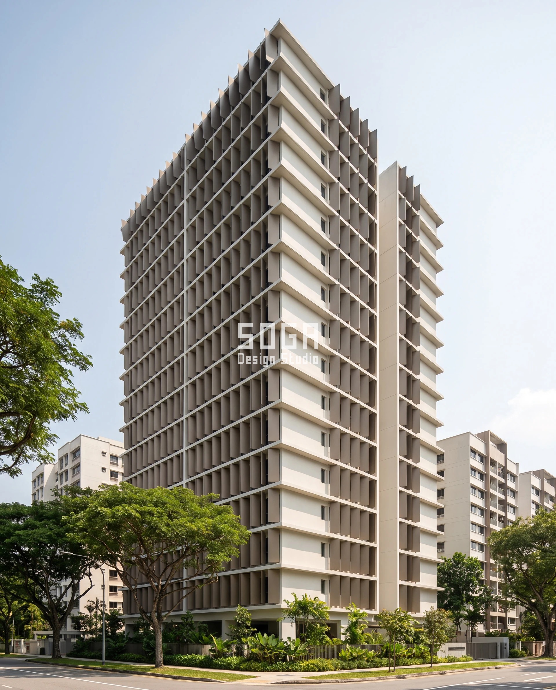
There is a third register worth knowing about, and the corner view above is it. Dead-on from 140 m the Paya Lebar blades are just legible at 0.59 degrees. From the street corner at 55 m, looking obliquely up the flank, the tilt that was almost invisible becomes the loudest thing on the building: the blades foreshorten, overlap and close into an almost solid warm-grey band across the upper floors while the lower floors stay open. Same blades, same 1,440 mm spacing, same 3 degrees per floor. A different angle of approach. On a corner plot the oblique view is usually the one most people get, and it is worth checking a tilt or a fold at 45 degrees before the dead-on elevation is signed off.
Three questions catch nearly every module-scale failure before it is drawn. What is the design viewing distance, taken as the larger of street width plus setbacks and one and a half times the height? Does the module clear nine millimetres per metre of that distance, and does it sit in the twenty-to-forty-five band? Does the variation accumulate to more than one degree across the run somebody can actually see at once? A no to any of the three means the move has not been designed for this building. It has been designed for a smaller one.
Indicative Facade Rates for the Six Concepts (2026)
Rates below are all-in bands for the elevation as built – skin, carrier, cavity, cavity barriers, fixings and the glazing line inside that package – quoted in the currency of the market each concept sits in. For reference, our published India band for a parametric facade runs Rs 800 to Rs 2,500 per sq ft depending on system and finish. Read these as bands, never as rates: coil width, coating batch size, tank capacity, hoist type and access hours all sit inside them, and on a small area the mobilisation alone can move the figure by a third. An itemised estimate is issued per project. Note the pattern down the table – the rate per square foot rises as the module grows, while the number of parts collapses. You are not paying for metal. You are paying for lifting, restraint and access.
| System / material | Indicative rate (per sq ft) |
|---|---|
| Bukit Timah, Singapore – Parametric Scale Course. Sand-cream glazed ceramic fish-scale shingles, 300 mm average on a 220 mm course rise, 36 to a floor course, on a stainless clip rail over a drained and back-ventilated 40 mm cavity. 108 shingles, roughly 340 sq m of elevation. | SGD 105 – SGD 165 per sq ft, all-in. What moves it: area, not geometry. 340 sq m is a small mobilisation, and the press tool, the scaffold and the setting-out survey cost the same as they would on ten times the area. |
| Al Barsha, Dubai – Parametric Arch Reveal. Nine pill-arch apertures at a 1,750 mm bay in a monolithic 250 mm blockwork band, 520 mm reveals turned on five reusable GRP formers, three-coat hand-floated sand-tone plaster, recessed frame line. | AED 85 – AED 140 per sq ft, all-in. What moves it: labour hours. Nothing here is bought as a panel, so the rate follows the plasterer’s day rate and the formwork cycle rather than a coil price. Cheapest per sq ft on this page, most site-labour-intensive per square metre. |
| Al Wasl, Dubai – Parametric Crease Rank. 3.0 mm 5052-H32 coil-coated bronze-tone metal plates, 1,150 x 1,050 mm, folded once on a vertical crease, 16 to a floor on T-rail and stainless helping-hand brackets over a drained 100 mm cavity. 96 plates. | AED 150 – AED 235 per sq ft, all-in. What moves it: the coating batch and the bracket count. The six fold angles add nothing at all – they are six stored settings on one press brake programme working one blank. |
| Tiong Bahru, Singapore – Parametric Fin Depth Rank. Olive-bronze anodised 6063-T6 extruded metal fins, 220 x 60 mm in 3,150 mm storey-height lengths at a 1,050 mm pitch, 28 to a floor on stainless cantilever arms with thermal break washers. 196 fins. | SGD 130 – SGD 205 per sq ft, all-in. What moves it: anodising. A single colour lot for all 196 fins is one tank booking with no second chance, which is why we do not let the order be split across two batches to chase a rate. |
| Paya Lebar, Singapore – Parametric Blade Tilt Rank. 2.5 mm 5005-H14 coil-coated warm-grey metal blades, 1,440 x 1,180 mm, pinned on a stainless vertical pivot at a fixed tilt, 32 to a floor across nineteen floors. 608 blades. | SGD 145 – SGD 225 per sq ft, all-in. What moves it: height. At nineteen floors the monorail hoist, the maintenance cradle reach and the tie-off spacing cost more than the blade does. The nineteen tilts live in a 40 mm turned pin and cost nothing. |
| Business Bay, Dubai – Parametric Blade Width Rank. 2.5 mm 5052-H32 coil-coated champagne-tone metal blades, 3,100 mm tall and 1,600 to 2,700 mm wide on a constant 2,900 mm bay, 14 to a floor on spigots with a sliding drift restraint. 322 blades. | AED 190 – AED 290 per sq ft, all-in. What moves it: mass and movement. At 62 kg and 3.1 m tall every blade is a mechanical lift with an inter-storey drift restraint, and that restraint is the expensive drawing on the job. Highest rate on this page, lowest part count. |
How SOGA Sizes the Module Before Any Pattern Is Drawn
The order of operations is fixed on every project we run, and the pattern is close to last. First the access study: how the facade will be cleaned, reached and replaced in twenty years, because the cradle reach, the mast climber width and the tie-off spacing put hard limits on bay width before anybody has drawn a module. That is why the Business Bay bay is 2,900 mm and not 3,400. Second the viewing distances, both of them on anything above ten storeys, taken off the site plan as street width plus setbacks against one and a half times the height. Third the module, sized from those distances by the nine-millimetres-per-metre floor and the twenty-to-forty-five band. Fourth the operation – one geometric move on the band system, never two. Only then the pattern.
The other half of the method is the tool count, and it is what keeps a graded facade at the same price as a flat one. Every system on this page holds its layout absolutely constant – the shingle pitch, the arch bay, the plate spacing, the fin pitch, the blade bay – and varies exactly one quantity. One press tool with nine width inserts for 108 shingles. Five GRP formers for eighteen arches. One press brake programme with six angle settings for 96 plates. One extrusion die and one anodising lot for 196 fins. One blank, one folding programme and nineteen pivot settings for 608 blades. One roll-form line and twenty-three slit widths for 322 blades. Unique parts across all six: zero. Second tools required: none. This is the same manufacturing logic set out in our work on how parametric facades became manufacturable and on one mould, many faces – and it is the reason the variation on these buildings is a line on a setting sheet rather than a line on an invoice.
What we do not claim is a measured field study. The half-degree floor is a working rule we size against, arrived at from optics and from what survives on a real elevation in rain and haze, and we state it as a rule rather than as a finding. Nor are these built projects: they are six concepts, drawn to buildable specification with real sections, real fixings, real weights and real access, so that the arithmetic in front of you can be checked rather than admired. If your own numbers land differently, the method still holds. Measure the distance, then size the module. The full system-by-system background sits in our parametric facade design pillar.
The same sizing discipline applies when the module driver is a regulatory greenery target rather than a viewing angle: see the floor-by-floor terrace depth and fascia amplitude table for a Singapore mall, sized level by level from a 2.0 m to 6.5 m terrace against Singapore’s Green Plot Ratio target.
For what this kind of shading is worth on an actual electricity bill, see does a facade reduce your AC bill.
Related Reading
- Retail Podium Facade Design: letting footfall set the gradient direction
- Parametric facade design in India: systems, materials and cost per sq ft
- Facade and elevation design in India: the complete FAQ guide
- Parametric architecture in India: contemporary facade design trends
- How a sequin facade is manufactured: scale, geometry and nesting yield
- How parametric facades became manufacturable in India
- Residential facade design in India, Dubai and Singapore
- Villa facade design cost in India, Dubai, Singapore and the UAE
Frequently Asked Questions
How big should a facade module be?
Size it from the viewing distance, not from the building. The working floor is that the module in millimetres should be at least nine times the design viewing distance in metres – 144 mm at sixteen metres, 360 mm at forty, 810 mm at ninety, 1,260 mm at a hundred and forty. That floor is where a module stops reading as a shape and starts reading as texture, at about half a degree of angular size. The floor is not the target: we design to twenty to forty-five times the distance in metres, roughly one to two and a half degrees, so the module holds its shape in haze, in rain and against a bright sky.
Does building height set the facade module size, or does street width?
Both, and you take whichever gives the larger distance. Street width plus both setbacks is where a pedestrian physically stands. One and a half to two times the building height is how far back you have to be to take the whole thing in. On a low building the street usually wins, which is why a two-storey villa on a wide Al Barsha road carries a far larger module than a three-storey house on a narrow Bukit Timah lane. On anything tall the height wins by a wide margin and the street stops mattering.
What is the most common mistake in sizing a facade panel for a high-rise?
Carrying a module up from a smaller building unchanged. Take a 300 mm shingle that works beautifully on a three-storey house and put it on a twenty-three-storey tower read from a hundred and forty metres: it subtends 0.12 degrees, a quarter of the legibility floor, so the whole elevation reads as a flat grey wash. On a 40.6 m by 75.9 m elevation that is 46,575 shingles and roughly 93,000 fixings, against 322 storey-tall blades for a module sized correctly. You pay a hundred and forty-five times the part count for something nobody can see.
How many facade modules should there be per floor?
Per floor is the wrong unit, because a tall building has a much wider elevation and will always carry more parts per floor whatever the module. Normalise it: modules per ten metres of elevation width. On the six concepts here that runs from 33 per 10 m on the three-storey house to 3.4 per 10 m on the twenty-three-storey tower – ten to one, over seven times the height. As a starting point, expect 14 to 36 per 10 m up to three storeys, 6 to 13 between seven and ten storeys, and 2 to 5 above nineteen.
Do larger facade modules cost more per square foot?
Usually yes per square foot, and usually less in total risk. Across the six concepts the rate rises as the module grows – from SGD 105 to 165 per sq ft for a ceramic shingle course up to AED 190 to 290 per sq ft for storey-tall blades – while the part count collapses from tens of thousands to a few hundred. The money is not in the metal. It is in lifting, restraint, sealed interfaces and access hours, all of which scale with the number of pieces. Every figure is a band, and an itemised estimate is issued per project.
Does a bigger module mean less parametric variation is possible?
No, but the variation changes character. On a small module the variation is dimensional: a 12 mm step per course accumulates to 100 mm and reads as a visible gradient. On a twenty-three-storey tower a 50 mm step per floor subtends 0.02 degrees and the full 1,100 mm accumulation only reaches 0.45 degrees, so nobody sees the blade get wider. What they see is the gap between blades closing from 1,300 mm to 200 mm – porosity falling from 45 to 7 per cent – which reads as tone. Above about twenty storeys you stop designing a dimension and start designing a tone.
How does SOGA fix the module size on a Singapore or Dubai project?
In a fixed order, with the pattern close to last. The access study comes first, because cradle reach, mast climber width and tie-off spacing cap the bay width before any module exists – that is why the Business Bay bay is 2,900 mm. Then both viewing distances off the site plan. Then the module, sized by the nine-millimetres-per-metre floor. Then one geometric operation on the band system, never two. Then the pattern, with the layout held constant and exactly one quantity varying, so the whole facade comes off one tool with zero unique parts.
Send Us the Street Width Before You Send Us the Elevation
If a facade module has been chosen before anybody worked out how far back the building is seen from, it has been chosen by the sheet size. SOGA Design Studio designs and details parametric facades for residential and commercial buildings across Singapore, Dubai and the wider UAE, and India. On every project we fix the access strategy, then the two viewing distances, then the module size, then the operation – in that order, with the numbers written into the fabrication drawings. Send the site plan, the storey count, the kerb-to-kerb street width and both setbacks to [email protected] and we will come back with the design viewing distance for your building, the module size band it implies, the per-floor count that follows, and an itemised estimate for the system that fits it.