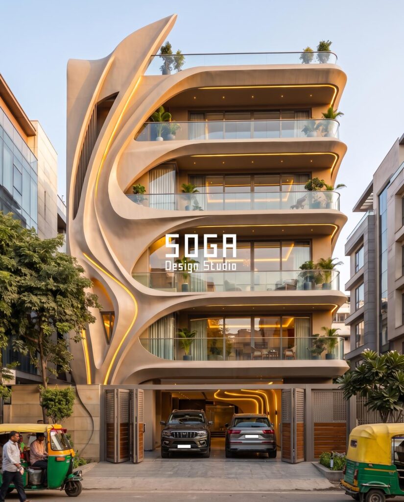
For most of the last decade, parametric architecture in India lived in two places: on presentation boards and in competition entries. The geometry was ambitious, the renders were convincing, and the buildings mostly did not get built. Two problems stopped them, and neither was a design problem. One was manufacturing skill. The other was cost.
This is an account of how those two problems were worked through — not solved by importing a system from elsewhere, but by re-engineering the geometry itself around what Indian fabricators can actually hold, what Indian sites can actually absorb, and what Indian project budgets can actually carry. It is a story about constraint, and about the unglamorous research that turns a shape into a system.
A manufacturable parametric facade is one whose geometry, tolerances and assembly sequence match the machines, skills and site conditions actually available to the project. In India this means panel families that repeat efficiently, forming operations local fabricators already run, fixings that absorb structural deviation, and drawings detailed enough that the shop floor needs no interpretation.
What “manufacturable” actually means in facade engineering
The word gets used loosely. In facade engineering it has a precise meaning: a design is manufacturable when every part of it can be produced, transported, handled and fixed by the specific supply chain that will build it — at a cost and a pace the project can sustain.
That is a much harder test than “can this be made”. Almost any geometry can be made once. The question is whether it can be made two thousand times, by a shop floor working shifts, with a rejection rate low enough that the project does not run out of material or time.
The gap between a rendered facade and a fabricated one
A render describes a surface. A facade is an assembly. Between the two sit a set of questions the render never answers.
How does this panel get from a flat sheet to a formed shape, and does that forming operation exist on the fabricator’s floor? What is the flat-pattern development, and how much material is wasted around it? How does the panel hold its shape once it is off the tool — does it spring back, and by how much? How does it hang, and what carries the load back to the structure? What happens where two panels meet, and what happens where the pattern meets a corner, a parapet, an expansion joint, a drainage outlet?
Each of those questions has an answer that changes the geometry. A facade system is what you have left after you have answered all of them and the design still looks like itself.
Three failure modes: geometry, tolerance and labour
Parametric facades in India failed for three recurring reasons, and it is worth naming them plainly because each one has a design response.
Geometry failure. The model contains too many unique parts. A pattern that varies continuously across an elevation can produce a situation where no two panels are the same. That is trivial in a model and ruinous on a shop floor, where every unique part means a new tool setting, a new drawing, a new inspection, and a new opportunity for a part to be made wrong. The design response is rationalisation: reducing the number of distinct parts to a small family while keeping the variation the eye actually reads.
Tolerance failure. The facade is designed to a precision the building cannot deliver. Reinforced concrete frames on Indian sites deviate. If a panel system has no adjustment built into its fixing, the deviation shows up as a visible misalignment across a long elevation — or, worse, as panels that will not fit at all. The design response is a fixing strategy with deliberate, documented adjustment in three axes, and a sequence that lets the installer take up error progressively rather than discovering it at the last bay.
Labour failure. The design assumes site skills that are not there. A system that requires a torque-controlled fixing at every point, or an alignment jig at every panel, will not survive contact with a working site. The design response is to move complexity into the workshop, where it can be controlled, and to leave site work as simple and as forgiving as possible. Every hour of judgment you can take off the scaffold is an hour of risk removed.
The Indian fabrication reality a parametric system must respect
There is a persistent assumption that Indian fabrication is a limitation to be worked around. In practice it is a specific capability profile — strong in some places, thin in others — and a system designed against that profile performs better than one adapted from elsewhere.
The machines that are actually on the floor
Most parametric facade work does not need exotic equipment. It needs the processes Indian metal fabrication already runs at scale: sheet cutting, punching, laser profiling, press-brake forming, rolling, welding, and a finishing line. The engineering effort goes into sequencing those processes and controlling what happens between them — not into acquiring machinery nobody has.
What varies enormously is repeatability. A press brake can hold an angle very well when it is set once and run for a long batch. It holds it less well across frequent tool changes. So the system’s cost is not driven by how complex a single panel is. It is driven by how often the fabricator has to stop and reset. Design the panel family so that the machine runs long batches, and a visually complex facade becomes economically ordinary.
Where hand skill outperforms automation — and where it does not
Indian fabrication carries a genuine strength that highly automated supply chains have partly lost: skilled hands that can finish, correct and assemble with judgment. On assembly operations, edge finishing and on-site adaptation, that skill is an asset, and a well-designed system uses it.
But hand skill is the wrong tool for dimensional consistency across thousands of parts. Anything that must be identical must be made by a machine against a jig, not judged by eye. The discipline is knowing which is which — and writing that division into the drawings, so the shop floor is not left to decide.
The research loop behind a facade system
None of the four systems described later in this article arrived as a design. Each arrived as a research programme that eventually produced a design.
Prototype, destructive test, fabrication trial, installation mock-up
The loop runs in that order, and it runs more than once.
A prototype answers whether the geometry can exist at all — whether the fold holds, whether the disc sits true, whether the overlap drains. It is usually made small and made badly, and its job is to fail early.
A destructive test answers where the assembly gives way: the fixing, the panel, or the substrate. You cannot design a fixing spacing honestly until you know what breaks first.
A fabrication trial moves the work onto a real production floor with real operators and real batch sizes. This is where most design assumptions die. A detail that was elegant on a drawing turns out to need a hand the operator does not have, or a tool change nobody costed. The trial produces the revisions that make the system economic.
An installation mock-up is a full-height or near-full-height section built the way the site will build it — including the substructure, including the sequence, including the mistakes. It is the only reliable way to find out how long a panel actually takes to fix, and therefore what the facade actually costs.
Then the loop repeats, because each stage changes the geometry, and changed geometry has to be re-tested.
Why a system takes six to twelve months
Because that loop cannot be compressed without transferring risk onto a project. Systems developed at SOGA typically ran through six months to close to a year of prototyping, structural study, fabrication trials and installation testing before they were offered on a live project.
That is a commercially uncomfortable amount of unpaid development. It is also the whole point. A system that has been through the loop arrives on site with a known panel family, a known fixing method, a known tolerance strategy and a known installation rate. A design that has not been through the loop arrives on site as a set of hopes.
R&D deliverable checklist for a new facade system
By the end of development, a system should have produced all of the following. If any is missing, it is not yet a system.
- A defined panel family, with the number of unique parts fixed and documented
- Flat-pattern development for every part type, with material yield calculated
- A forming sequence that a fabricator can run without special-purpose tooling, or with tooling whose cost is known
- A fixing detail with adjustment in three axes and a stated adjustment range
- Load path documentation from panel to primary structure
- A finishing specification with process controls, not just a colour reference
- An installation sequence with a measured rate per panel from the mock-up
- A replacement procedure for a single damaged panel, without dismantling neighbours
- A drawing set detailed enough that the shop floor asks no questions
- A tolerance schedule reconciling structure, substructure and panel face
Designing for a budget without designing a compromise
The most common misunderstanding about parametric facades is that cost tracks visual complexity. It does not. Cost tracks part count, tool changes, handling operations and installation hours — and those four things are only loosely related to how complex the facade looks.
This is genuinely good news for design, because it means the levers that reduce cost are not the levers that reduce ambition. A facade can hold a continuously varying pattern across a whole elevation while using a small number of distinct parts, if the variation is carried by position and rotation rather than by shape. Rotate a repeated element through a controlled range and the eye reads continuous variation; the shop floor reads one part, made many times.
That single insight — variation through placement rather than through form — is the foundation of every system described below, and it is what made the difference between a concept that stays on a board and a product that goes on a building.
| Attribute | Experimental one-off | Engineered system |
|---|---|---|
| Unique part count | Often in the hundreds or thousands | A defined family, fixed and documented |
| Tooling changes | Frequent, uncosted | Batched and planned into the production sequence |
| Drawing-set maturity | Design intent; shop floor interprets | Fabrication-ready; no interpretation required |
| Tolerance strategy | Assumed, discovered on site | Documented, with adjustment range stated per axis |
| Installation labour | Unknown until it happens | Measured on a mock-up before pricing |
| Repair path | Area replacement | Single-panel replacement without disturbing neighbours |
| Cost predictability | Wide; risk sits with the contractor | Narrow; risk retired during development |
| Programme risk | High — problems surface at installation | Low — problems surfaced during fabrication trials |
Tolerance is the real design constraint
If there is one idea worth carrying away from this article, it is this: on a parametric facade, tolerance is not a technical afterthought. It is the primary design constraint, and it should be resolved before the pattern is.
Structure tolerance, panel tolerance, perception tolerance
Three different tolerances have to be reconciled, and they operate at different scales.
Structure tolerance is what the building gives you. A cast frame deviates from its theoretical position — in plan, in level, and in plumb. Those deviations are normal and are covered by construction standards; the facade has to absorb them, not argue with them.
Panel tolerance is what the workshop gives you. It is much tighter than structure tolerance, and it accumulates: a small error in a flat pattern becomes a larger error after forming, and a larger one still after assembly.
Perception tolerance is what the eye accepts, and it is the strictest of the three. A human eye reading a long horizontal line will detect a deviation far smaller than either of the other tolerances allow. This is why facades that meet every written specification can still look wrong.
The design task is to build a system where structure tolerance is absorbed by adjustable fixings, panel tolerance is controlled by jigs and inspection, and perception tolerance is protected by choosing which lines the eye will read — and then making only those lines perfect. A facade with a deliberate shadow gap at every joint hides deviation; a facade with a continuous flush plane advertises it.
Four systems, one engineering method
Four facade systems came out of this method, and SOGA develops and documents each of them as a named system: the SOGA Coin Facade, the SOGA Sequin Facade, the SOGA Slicing Fin Facade and the SOGA 3D Block Facade. They look nothing alike. Underneath, they solve the same problem the same way — variation through placement, complexity moved into the workshop, adjustment built into the fixing.
The SOGA Coin Facade
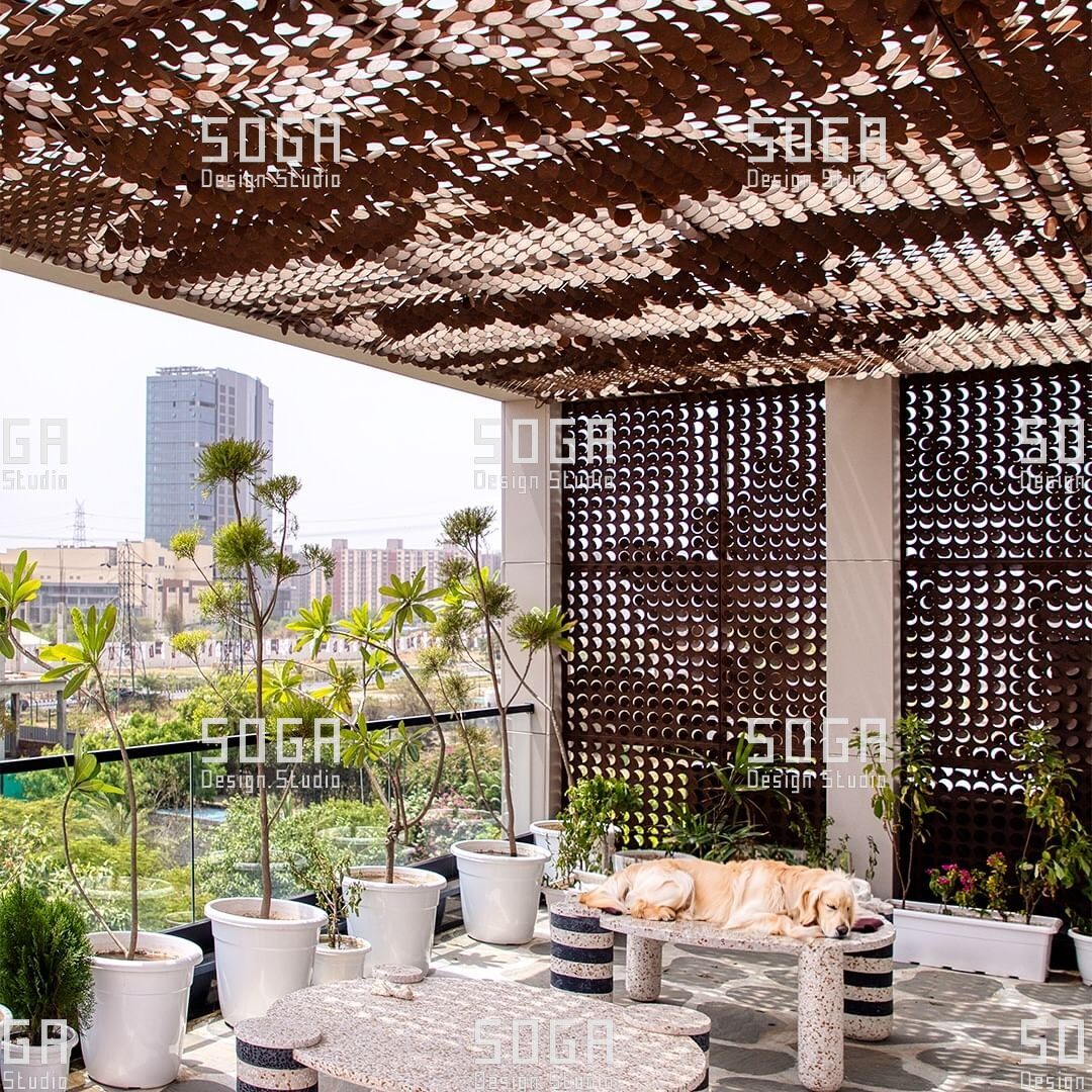
A field of circular formed elements carried on a supporting frame or spine. Variation comes from diameter, spacing and rotation angle, which means a facade can shift smoothly from dense to open across an elevation while the workshop makes a small number of disc types.
The engineering questions are specific to the geometry: how the disc is held so it does not chatter in wind, how the edge is formed so it reads as a solid object rather than a cut sheet, and how a single damaged disc comes off without touching its neighbours. Because the system is open, it also does useful work — filtering daylight, screening views, and letting air move behind the skin.
The SOGA Sequin Facade

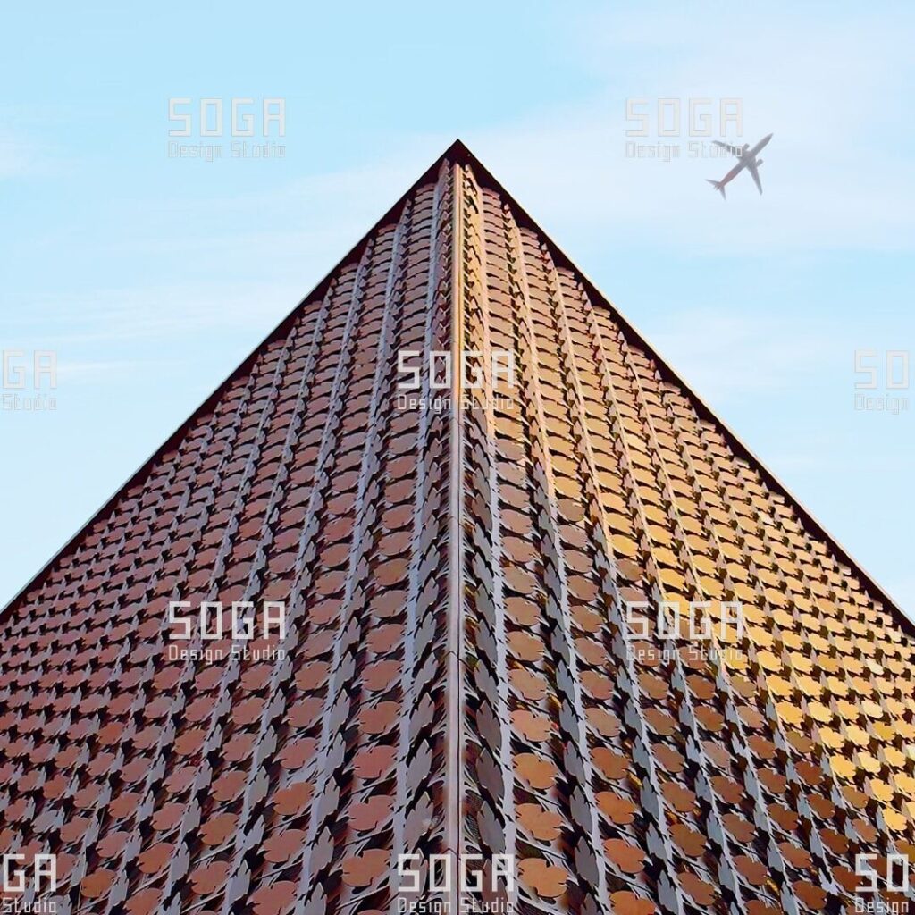
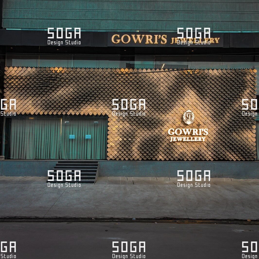
An overlapping field of small scale-like elements, laid like tiling rather than fixed like cladding. The overlap is the whole system: it controls how the surface drains, how much movement each element can take without binding, and how light breaks across the elevation.
The hard part is not the individual scale — it is the carrier and the nesting. Scales have to be laid out on stock material so that the yield is acceptable, and they have to hang on a carrier that keeps the courses straight while allowing each element enough freedom to sit against a wall that is not flat. Done well, the result is a surface that changes completely between flat daylight and raking evening light.
The SOGA Slicing Fin Facade
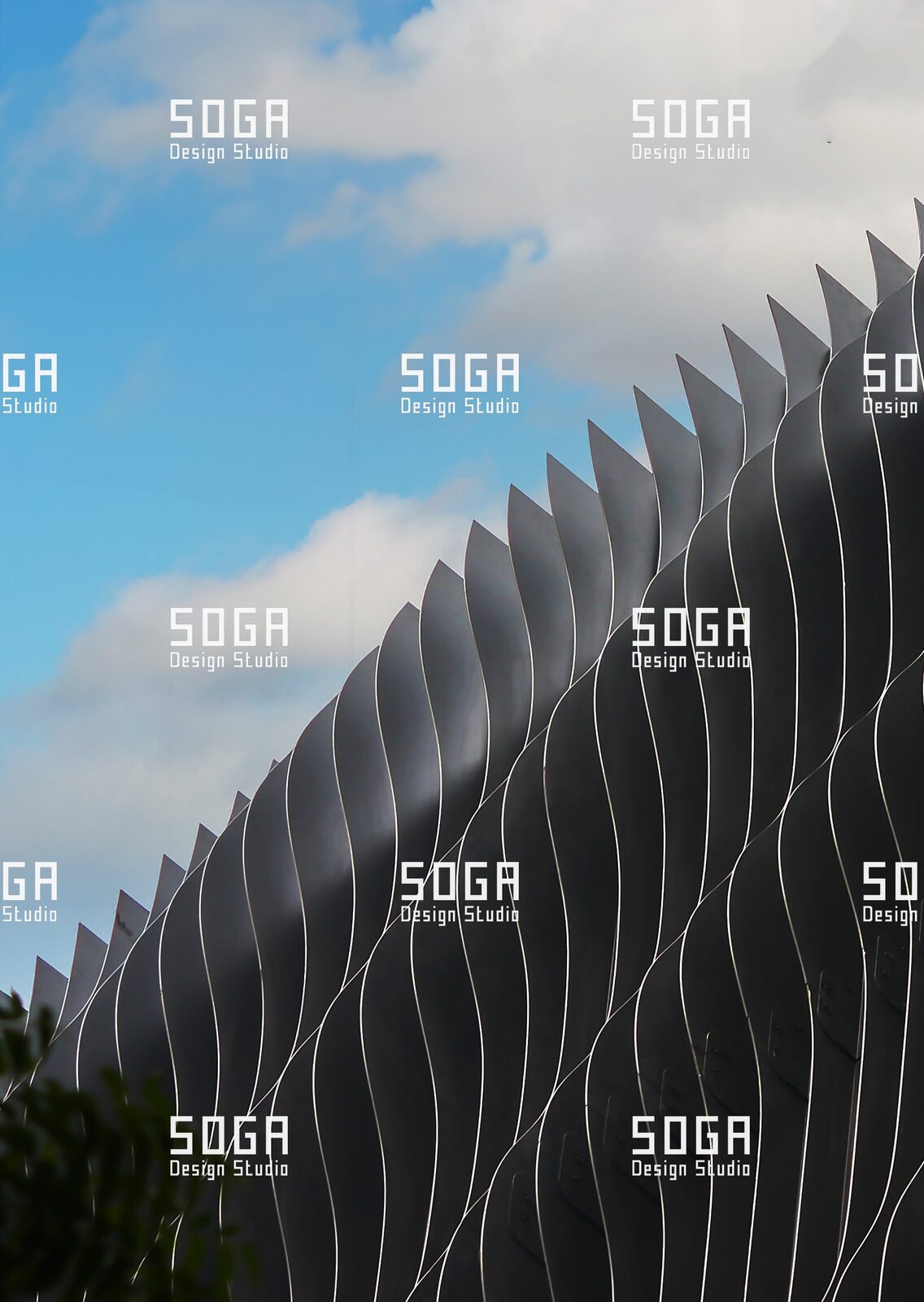
A field of vertical fins whose profile changes progressively along the elevation, so a flat wall reads as a curved or twisting surface. It is the most direct of the four systems to explain and the most demanding to fabricate, because every fin is a different profile and each one has to stay straight.
Twist control is the central problem. A long, thin element wants to move after cutting and after forming, and a fin that has twisted by a small amount is visible from the street. The system’s development was largely about profile design, restraint spacing, and a bracket that could set both position and angle on site without a jig.
The SOGA 3D Block Facade
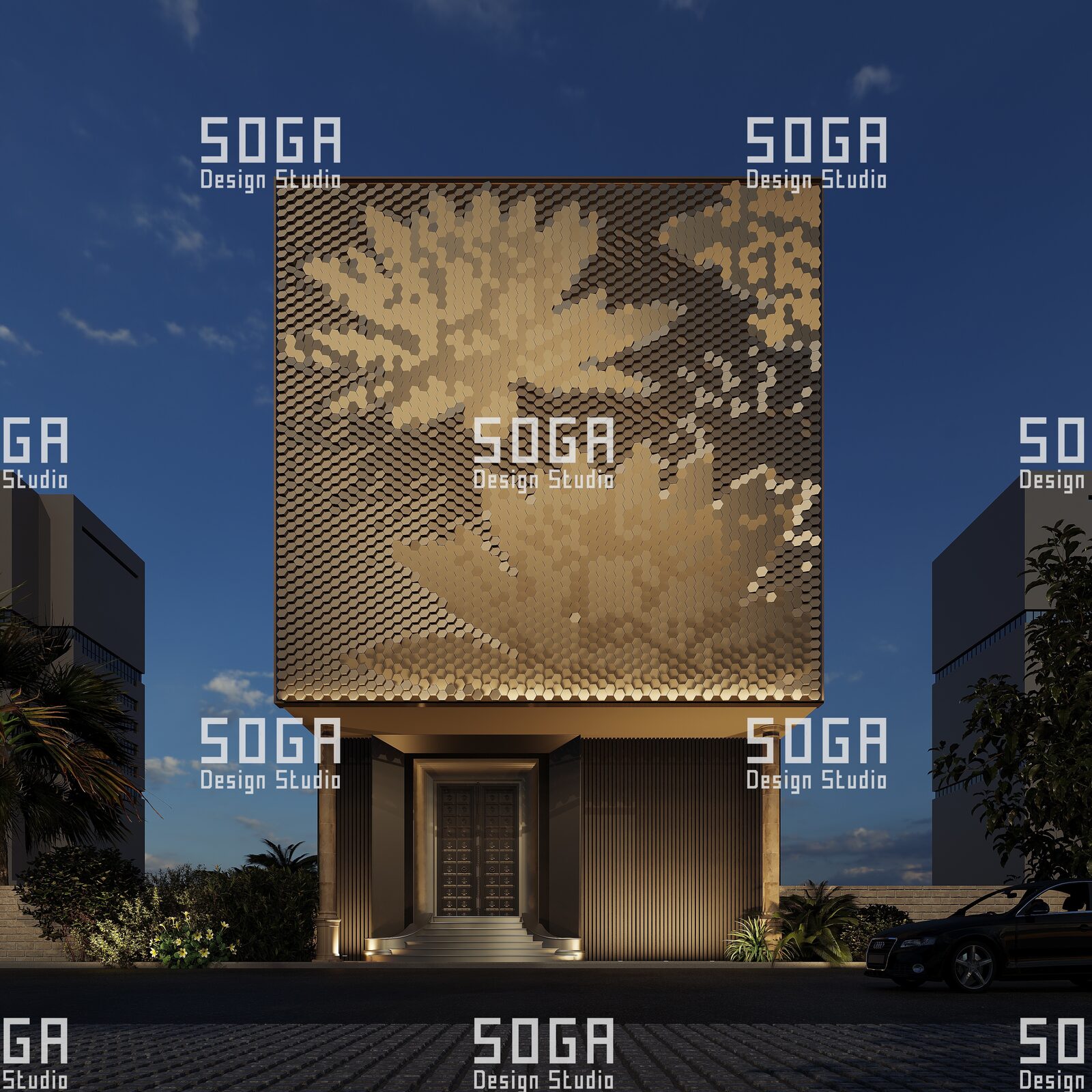
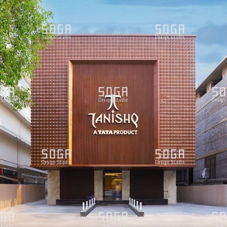
A modular field of formed blocks whose projection depth varies panel by panel, turning an elevation into a low relief. Depth carries the image; the module carries the economics.
The engineering problems are rigidity and flatness. A panel with deep folds is stiff in one direction and weak in another, and the fold geometry has to be developed so the panel holds a true face without oil-canning. Beyond that, the discipline is arithmetic: how many depth steps are needed for a pattern to read, and how few can you get away with — because every additional depth step is another tool setting on the floor.
| SOGA Coin | SOGA Sequin | SOGA Slicing Fin | SOGA 3D Block | |
|---|---|---|---|---|
| Visual effect | Shimmer and view-through | Scale texture, light break | Apparent curvature from flat wall | Low-relief depth pattern |
| Variation carried by | Diameter, pitch, rotation | Overlap, gradient, density | Profile progression | Projection depth |
| Openness | Open — screening system | Closed to semi-closed | Open — shading system | Closed — cladding system |
| Primary engineering risk | Wind chatter, disc restraint | Nesting yield, carrier straightness | Twist and deflection | Flatness, fold rigidity |
| Typical application | Screens, retail elevations, service zones | Retail and hospitality elevations | Shading, tall elevations, curved reads | Large flat elevations, signage walls |
| Single-part replacement | Yes | Yes | Yes | Panel-level |
| Substructure demand | Moderate | Moderate | High | Moderate |
Exporting the method: India, Dubai and Singapore
The method did not originate in isolation. It came out of years of practice in Singapore, where facade documentation standards are unforgiving and the gap between a design drawing and a fabrication drawing is understood as a discipline in its own right. Bringing that documentation culture back and applying it to Indian fabrication capability is, in short, what the studio did. An early collaboration with an Indian metal facade manufacturer helped test those workflows against real production conditions.
What is interesting is that the method travels in both directions. Systems developed against Indian manufacturing constraints turn out to be well suited to Gulf and Southeast Asian projects, because the design discipline that makes a facade affordable in India — low unique-part count, forgiving fixings, simple site operations — makes it fast and reliable anywhere.
SOGA Design Studio is a parametric and computational architecture practice based in Gurugram, working across India, Dubai and Singapore, specialising in facade systems engineered for local fabrication.
How to test whether a parametric facade is buildable on your project
If you are an architect, consultant or developer assessing a parametric facade proposal, these are the questions that separate a system from a picture. Ask them early, before the design is fixed.
- How many unique parts are in this facade? If nobody can answer with a number, the design has not been rationalised.
- What forming operations does each part need, and does the intended fabricator run them today? Not “could acquire” — runs today.
- What is the material yield? A pattern that nests badly can waste a large fraction of every sheet, and that waste is in the price whether or not it is itemised.
- What adjustment does the fixing allow, in which axes, and over what range? Then compare that range against the structural tolerance the frame is actually being built to.
- Has a 1:1 mock-up been built, and what installation rate did it produce? A measured rate is the difference between a priced facade and a guessed one.
- How is a single damaged panel replaced? If the answer involves removing neighbouring panels, maintenance cost over the building’s life will be significant.
- Who owns the fabrication drawings, and how detailed are they? A drawing set that requires interpretation on the shop floor will be interpreted — and not always the way you intended.
Any proposal that answers all seven clearly is buildable. Any proposal that answers fewer than five is still a concept, whatever the renders suggest.
Frequently asked questions
Are parametric facades affordable in India?
They can be, when the geometry is rationalised into repeating panel families instead of unique parts. Cost is driven far more by part count, tooling changes and installation labour than by how complex the pattern looks.
Do Indian fabricators have the equipment for parametric facades?
Most parametric facade work uses cutting, forming and finishing processes already common in Indian metal fabrication. The engineering effort goes into sequencing and tolerance control, not into exotic machinery.
How long does it take to develop a new facade system?
Each system went through roughly six months to close to a year of prototyping, structural study, fabrication trials and installation testing before being offered on a live project. That development is what makes site delivery predictable.
What is the difference between a parametric design and a parametric system?
A design is a one-off geometry. A system carries a documented panel family, fixing method, tolerance strategy and installation sequence that can be repeated across projects with a known cost and a known programme.
Where this goes next
Nothing in this article is proprietary thinking. It is the ordinary discipline of facade engineering, applied to geometry that had not previously been treated as an engineering problem in this market. The reason it is worth writing down is that the alternative — a decade of parametric architecture that stays on paper — was a real cost to Indian architecture, and it did not need to happen.
The ambition was never a single building. It was that India should develop its own vocabulary in parametric architecture rather than importing systems wholesale — designed here, engineered here, and good enough to be built anywhere.
If you are assessing whether a parametric facade is realistic for your project’s budget and fabrication route, our system documentation sets out the constraints openly — including the ones that rule a system out.
For the design side of the same question — why some facades are memorable at all — see the five qualities that make a facade iconic.