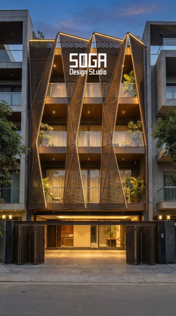
Elevation working drawings are the dimensioned, scaled set that turns an elevation design into something a contractor can price, fabricate and build without guessing. A render shows intent. A working drawing set carries the setting-out grid, module sizes, joint widths, substructure positions, fixing types and edge conditions — every number a site needs to reproduce the design at full size. In India a house elevation set typically runs 8 to 22 sheets.
Almost every elevation that disappoints its owner was approved as a picture and handed over as a picture. The mason then invented the parts the picture did not describe: the joint width, the corner return, the point where the screen meets the parapet. Those inventions are what you see from the road afterwards.
This guide sets out the seven drawings that actually get an elevation built, what each one must carry, who draws it, the order to buy them in if the budget is tight, and the four checks that separate a complete set from a decorative one. The design studies illustrated throughout are SOGA concepts.

Why A Render Is Not A Buildable Instruction
A render resolves at the scale of a screen. A facade resolves at the scale of a hand. Between those two scales sit roughly forty decisions that the render either averages out or hides in shadow, and every one of them has to be made by somebody before the elevation can be built.
The test is simple. Take any elevation image and ask: how wide is the gap between two adjacent panels? A render will not tell you. It might be 6 mm, it might be 25 mm. At 6 mm the facade reads as one continuous surface and every fabrication error shows. At 25 mm it reads as separate units and the shadow hides a great deal. Those are two different buildings, and the picture is identical.
The same question repeats for the depth of the reveal at every window, the way the screen stops at the parapet, what happens at the external corner, how the skin passes a rainwater downpipe, and where the substructure lands relative to the slab edge. A working drawing set answers all of them on paper, before anybody buys material.
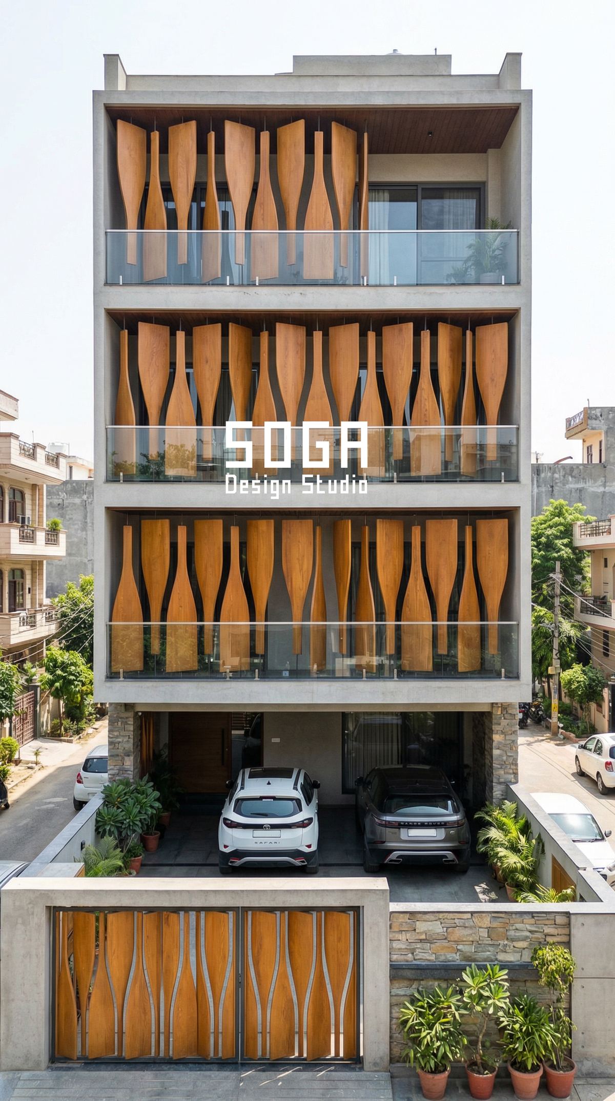
The Seven Drawings That Get An Elevation Built
A complete residential elevation set is not one drawing at a larger scale. It is seven documents doing seven different jobs, usually issued in this order.
| Drawing | What it does | Typical scale |
|---|---|---|
| 1. General arrangement elevation | Locates the whole design on the real building — levels, plot width, floor heights, the outline of every element | 1:50 |
| 2. Setting-out drawing | Gives the grid every module is measured from, with fixed datum lines in both directions | 1:50 with 1:20 insets |
| 3. Module and panel schedule | Numbers every unit, states its size and finish, and says how many of each are needed | Schedule, not scaled |
| 4. Substructure and fixing drawing | Shows brackets, rails, anchor positions and their distance from the slab edge | 1:20 |
| 5. Typical section through the skin | Cuts through the facade to show cavity, insulation, drainage and the air gap | 1:5 or 1:10 |
| 6. Junction and edge details | Resolves parapet, sill, soffit, external corner, expansion joint and downpipe crossing | 1:5 |
| 7. Fabrication or shop drawings | The fabricator’s own drawings of each part, dimensioned to the cutting list | 1:10 to 1:1 |
Drawings 1 to 6 are the designer’s responsibility. Drawing 7 is the fabricator’s, produced from 1 to 6 and returned for approval before cutting begins. A set that stops at drawing 1 is a picture with dimensions on it, and it is the single most common thing handed to an Indian house contractor.
The order matters as much as the content. Issuing a panel schedule before the setting-out drawing exists means the panel sizes were chosen before anyone knew what they had to fit into, which is how a facade ends up with a 180 mm sliver panel at one end of an otherwise regular frontage.

What The Setting-Out Drawing Must Carry
This is the drawing most house projects skip, and skipping it is the reason so many built elevations look subtly crooked next to their render. It establishes where every measurement starts.
A setting-out drawing needs a horizontal datum — one line, usually finished floor level at the ground floor, that every vertical dimension refers back to. It needs a vertical datum, normally one edge of the structural grid rather than the plot boundary, because plot boundaries in Indian plotted development are rarely square. And it needs the module pitch stated as a running dimension, not a repeated one.
Running dimensions, not repeated ones
If a screen has twelve bays at 1,150 mm, do not write “1150 (typ.)” twelve times. Write the cumulative dimension: 1150, 2300, 3450 and so on to 13,800. Repeated dimensions let each bay absorb its own small error, and by bay twelve the accumulated drift can exceed 40 mm. Running dimensions force every bay back to the datum, so error cannot compound.
This one change to a drawing costs nothing and is the difference between a screen that lines up with the parapet and one that dies 40 mm short of it.
The closing bay is a design decision
No frontage is an exact multiple of the module. Something has to absorb the remainder. The set must say what: a wider joint distributed across all bays, one deliberately different end bay, or a plain margin at both ends. Left unstated, the site will put the entire remainder into the last bay, on whichever end it reaches last.
Distributing 90 mm across twelve joints adds 7.5 mm to each and is invisible. Putting 90 mm into one bay is the first thing a visitor sees.
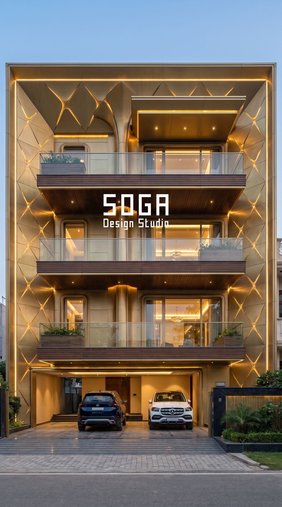
Who Draws What, And Where Sets Break Down
Most disputes on Indian house elevations are not disagreements about design. They are gaps where each party assumed the other was drawing something.
| Document | Who produces it | Who approves it |
|---|---|---|
| General arrangement, setting-out, schedules, sections, details | Facade designer or architect | Owner and main contractor |
| Structural check on the supporting frame | Structural consultant | Main contractor |
| Shop and fabrication drawings | Facade fabricator | Facade designer, then owner |
| Site survey of the built frame | Main contractor | Facade designer and fabricator |
| Method statement and installation sequence | Facade contractor | Main contractor |
The gap that opens most often is the fourth row. The facade is designed against the drawn frame, fabricated against the drawn frame, and then installed on the built frame, which is never identical. Somebody has to measure the real building and reconcile it before production starts. On a house that step is skipped perhaps four times in five.
Name it in the contract. One line — the main contractor shall provide a dimensioned survey of the completed frame before facade fabrication commences — prevents the most expensive category of elevation rework there is.
How To Buy The Set If The Budget Is Tight
A full drawing set is priced per project, because it moves with plot width, floor count and how much geometry the design carries. What is worth knowing before you ask anyone for a number is the order of importance, because a partial set bought in the right order still builds broadly right, and one bought in the wrong order does not.
Buy them in this sequence.
| Priority | Document | What you lose without it |
|---|---|---|
| 1 | Setting-out drawing with datums and running dimensions | Modules drift; the screen fails to meet the parapet |
| 2 | Junction and edge details — corner, parapet, sill | The places facades actually fail are improvised on site |
| 3 | Panel schedule with part numbers | Nobody has counted the parts, so nobody can price or order them |
| 4 | Substructure and fixing drawing | How the skin is held becomes the fabricator’s guess |
| 5 | Typical section through the skin | Cavity, drainage and the air gap stay undefined |
| 6 | General arrangement elevations | Useful, but recoverable from the setting-out drawing |
A design with the first three and no section will still build broadly right. A design with a beautiful section and no setting-out drawing will not, because nothing tells the site where anything starts.
The comparison worth running is not drawing-set against no drawing-set. It is drawing-set against the cost of rebuilding a bay that was set out from a picture — and on any Indian house that rebuild, in materials and programme together, is the larger number. Most elevations that go wrong go wrong in more than one bay.

Four Checks That Tell You A Set Is Real
You do not need to read construction drawings fluently to audit a set. Four questions do most of the work.
- Pick any two adjacent panels and ask for the joint width in millimetres. If the answer is a number, the set is real. If the answer is “as per site”, it is not.
- Ask what happens at the external corner. Every elevation has at least one. A real set has a 1:5 detail; a decorative set has a mitre drawn freehand or nothing at all.
- Ask where the substructure lands relative to the slab edge. If the bracket needs 120 mm of slab and the slab projects 75 mm, that is a redesign, and it is much cheaper to find on paper.
- Ask for the panel schedule and count the part numbers. A frontage with 96 units and one part number is repeating properly. The same frontage with 96 part numbers is not a system, it is 96 separate problems.
Ask these before fabrication is ordered, not after delivery. Every one of them is answerable in a meeting; none requires a site visit.
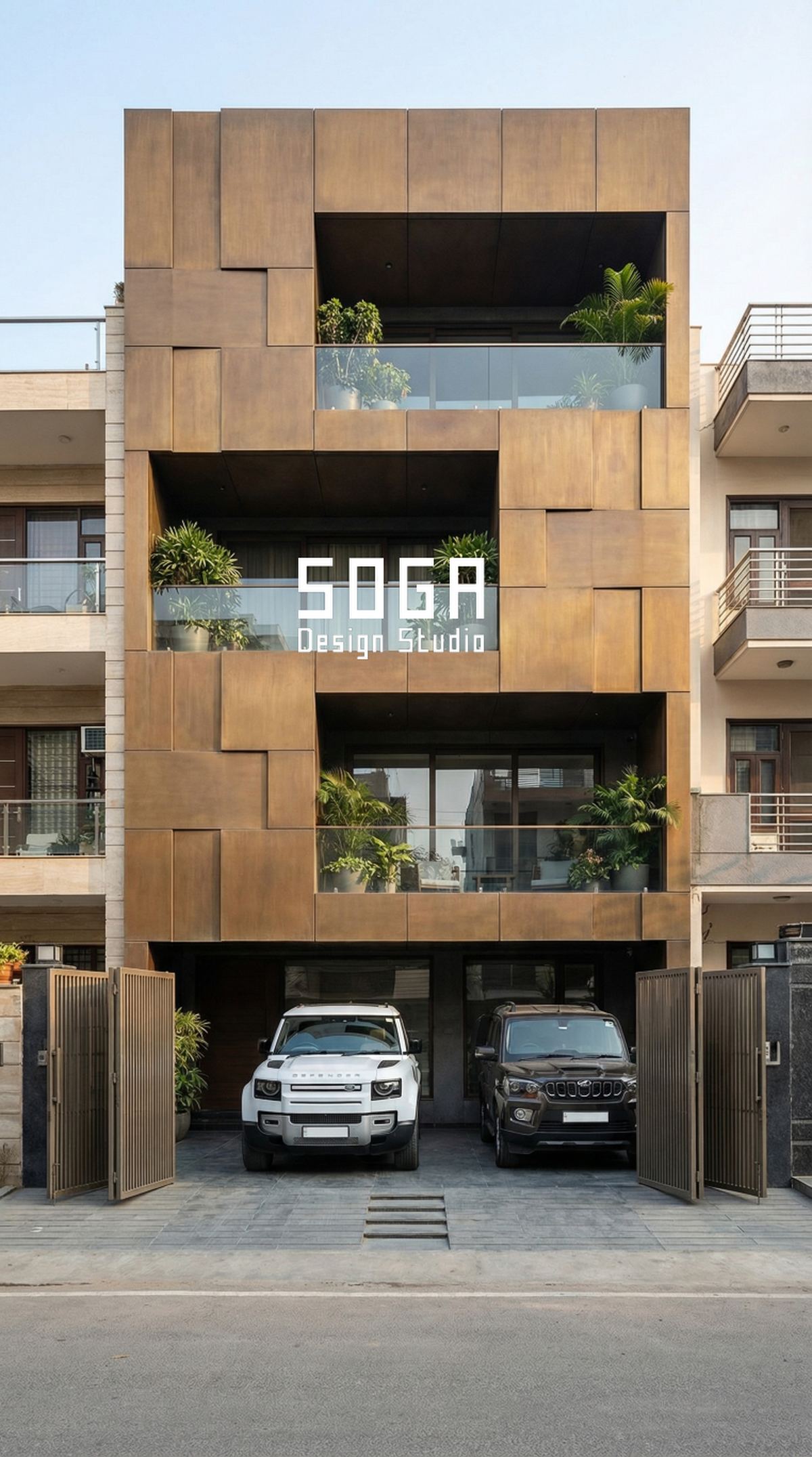
When To Start The Set, And How Long It Takes
The commonest programme mistake on an Indian house is starting the elevation drawings after the frame is up. By then the two things that most constrain the facade — where the slab edge actually is, and whether the columns can take a bracket — are fixed, and every awkward answer costs money instead of an eraser.
The elevation set should start when the structural drawings are issued and be substantially complete before the first slab above ground is cast. That is not because the facade is built then; it is because that is the last moment at which the facade can still ask the structure for anything.
| Stage | What the elevation set should be doing | Typical duration |
|---|---|---|
| Structural drawings issued | Concept and general arrangement; agree slab edge and parapet line | 2–3 weeks |
| Before ground floor slab is cast | Setting-out drawing; issue the frame tolerance note | 1–2 weeks |
| Frame under construction | Sections, junction details, panel schedule | 3–5 weeks |
| Frame complete, before fabrication | Site survey reconciliation; revised setting-out | 1–2 weeks |
| Fabrication ordered | Shop drawing review, one to three cycles | 2–4 weeks |
Total designer time is roughly eight to twelve weeks spread across the build, not a single block. Almost none of it sits on the critical path if it is started at the right moment, and almost all of it does if it is started late.
Two requests are worth making early because they are free before the frame is cast and expensive afterwards: keep the slab edge in one line across the frontage, and give the facade a nib or an upstand at the parapet to fix into. Neither costs the structure anything meaningful. Both remove a whole category of detailing problem.
What Changes When The Design Is Curved Or Parametric
Everything above assumes a facade of repeated flat units. A curved, folded or gradient facade is documented the same way but with three additions, and skipping them is why parametric designs so often build badly in India.
First, a curve cannot be dimensioned by its outline. It has to be given as a series of offsets from a straight datum line at a fixed spacing — typically every 300 mm or 600 mm — so a fabricator can reproduce it without owning the model. A drawing showing a smooth curve with two radii marked on it is not buildable information unless the curve genuinely is two arcs.
Second, a gradient facade where a parameter changes across the frontage needs a table, not a description. If the fin depth runs from 60 mm to 240 mm across eighteen bays, list all eighteen values. Written as “varies 60–240 mm”, the site will interpolate by eye, and by eye means in even steps that do not match the design.
Third, state how many distinct part numbers the design is allowed. A parametric facade that produces a unique part for every position is buildable in theory and ruinous in practice on a house. Rationalising eighteen fin depths into five repeated types, arranged so the eye still reads a smooth progression, is the difference between a facade that gets built and one that gets value-engineered into flat panels halfway through.
The Honest Limit Of A Drawing Set
Drawings control dimensions. They do not control workmanship, and they cannot make an unbuildable idea buildable.
A set can specify a 12 mm joint and a fabricator can still deliver panels cut to 14 mm. What the drawing does is make that a measurable failure with a named tolerance rather than an argument about taste. That is worth a great deal, but it is not the same as a guarantee.
The second limit is more important. If a design needs 96 different part numbers to build, no drawing set rescues it — it will be slow, expensive and full of errors however well it is documented. Drawings are where you discover that, which is exactly why they should come before the material order and not after it. Rationalising a design down to six part numbers is a design act, and it happens at the drawing board or it does not happen at all.
Frequently Asked Questions
How many drawings does a house elevation actually need?
Between 8 and 22 sheets for a typical Indian G+3 house, covering seven document types: general arrangement, setting-out, panel schedule, substructure and fixing, a section through the skin, junction details, and the fabricator’s shop drawings. Below about 8 sheets something in that list is missing, and it is usually the setting-out drawing.
Which drawings should I buy first if I cannot afford the full set?
In this order: the setting-out drawing with datums and running dimensions, then the junction and edge details for corner, parapet and sill, then the panel schedule with part numbers. A design with those three and no section will still build broadly right. A design with a beautiful section and no setting-out drawing will not, because nothing tells the site where anything starts.
Can my contractor build the elevation from a 3D render?
He can build something from it, but not that design. A render does not carry joint widths, module pitch, substructure positions or edge conditions, so those get decided on site by whoever reaches them first. That is why built elevations so often read as a coarser version of the image that was approved.
What is a setting-out drawing and why does it matter so much?
It fixes the horizontal and vertical datum that every other dimension is measured from, and states module pitch as running rather than repeated dimensions. Without it, small bay-by-bay errors accumulate; across twelve bays the drift can exceed 40 mm, which is why a screen ends up not meeting the parapet it was drawn to meet.
Who is responsible for measuring the building before fabrication?
The main contractor should provide a dimensioned survey of the completed RCC frame, which the facade designer and fabricator then reconcile against the drawings before production. On Indian house projects this step is skipped roughly four times in five, and it is the single largest cause of expensive elevation rework.
Related Reading
- Parametric facade design in India — the pillar guide
- What a facade design company in India actually delivers
- Elevation site checklist: what to inspect at each stage
- The elevation mockup: build one bay before the whole face
- Facade panel joint width and thermal movement in India
- Facade fixing brackets and anchors into an RCC slab
Get Your Elevation Drawn Properly
SOGA Design Studio produces complete elevation working drawing sets for plotted houses across India — setting-out, schedules, substructure, sections and junction details, plus shop drawing review through fabrication. If you have a design you like and a contractor asking how to build it, that gap is exactly what we document. Talk to us about your elevation.
Drawings also have to carry the lighting: conduit routes, driver niches and access. See what has to be built into an elevation before the skin closes.