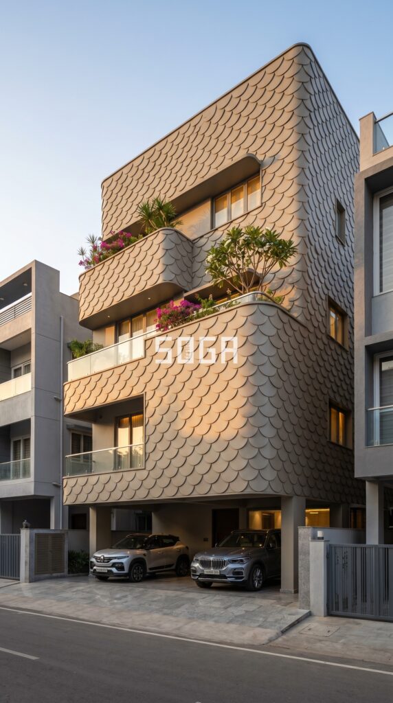
A facade panel joint is the deliberate clear gap between two adjacent cladding panels – the shadow gap you can see, and the movement space you cannot. Facade panel joint width is set by thermal movement first and by everything else second: how far the panel grows when its dark surface reaches 85 °C on a May afternoon, how accurately the press brake holds the cut length, how accurately the substructure was set out, and how much clear gap has to survive at the hottest hour of the year so that two panels never touch. On a 1.2 m aluminium panel that sum comes to 6 mm. On a 6 m aluminium panel the same reasoning gives 14 mm. This post shows the working that gets you from one to the other, with the coefficients, the temperature assumptions and the worked widths a detailer can put straight onto a drawing.
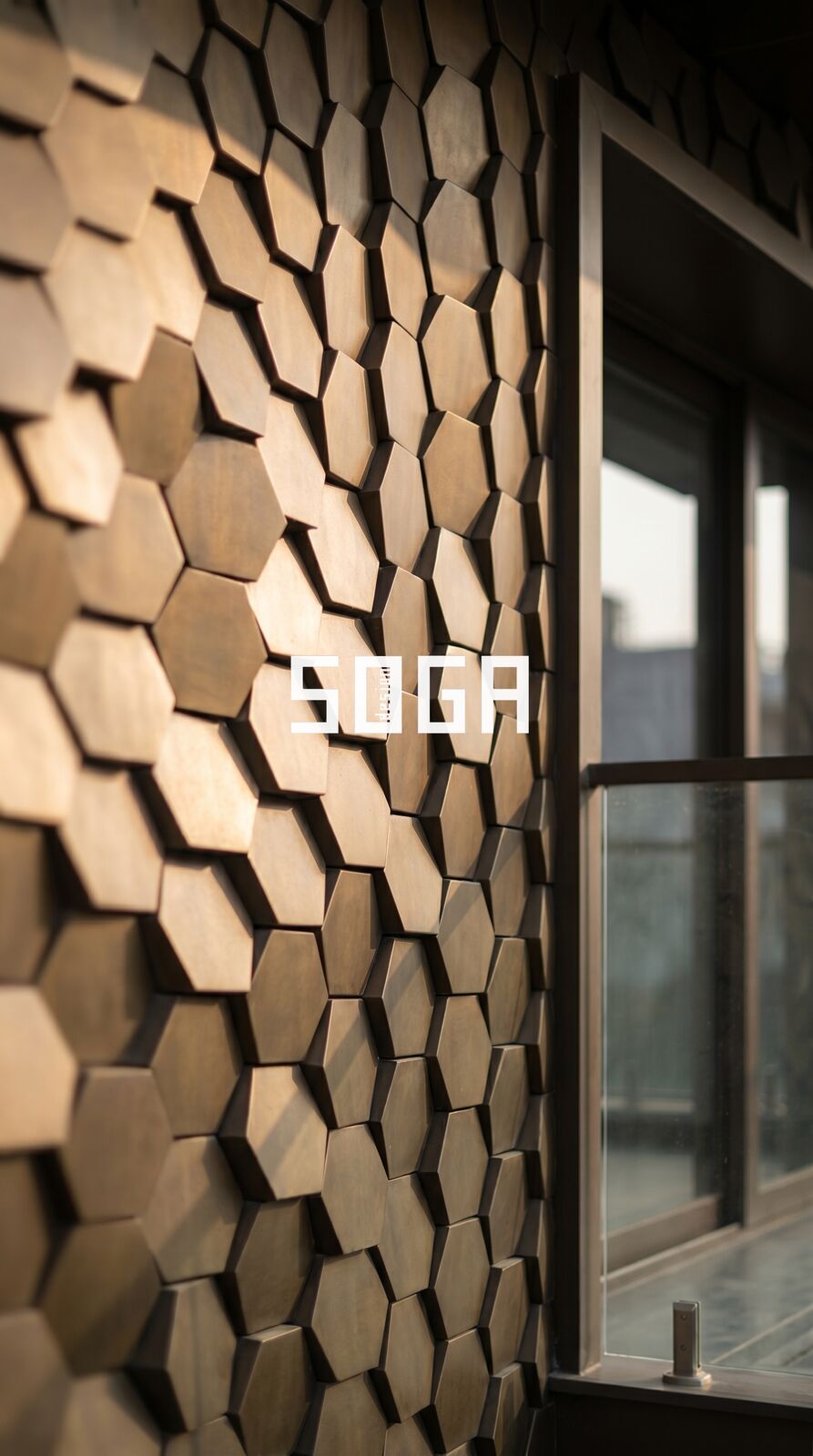
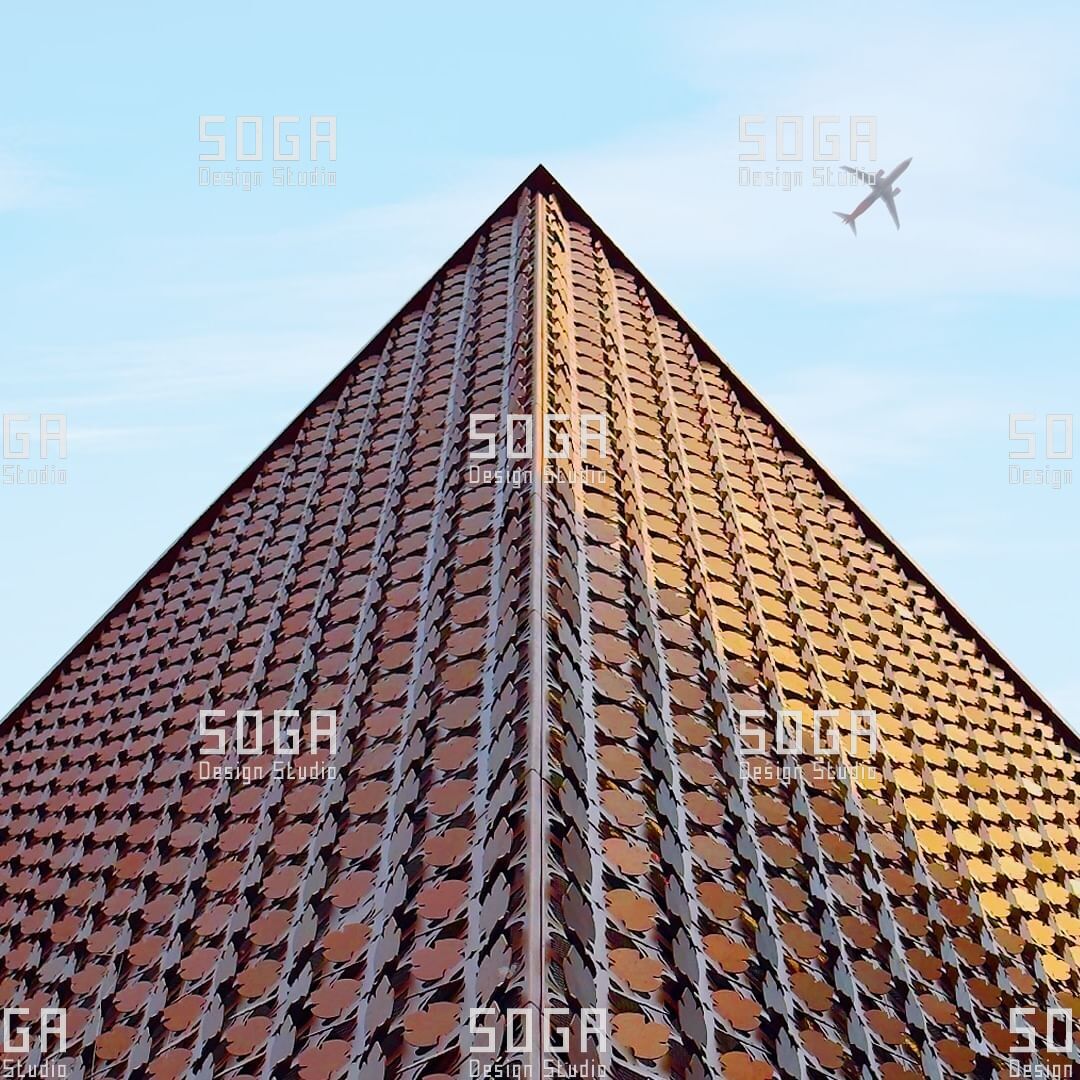
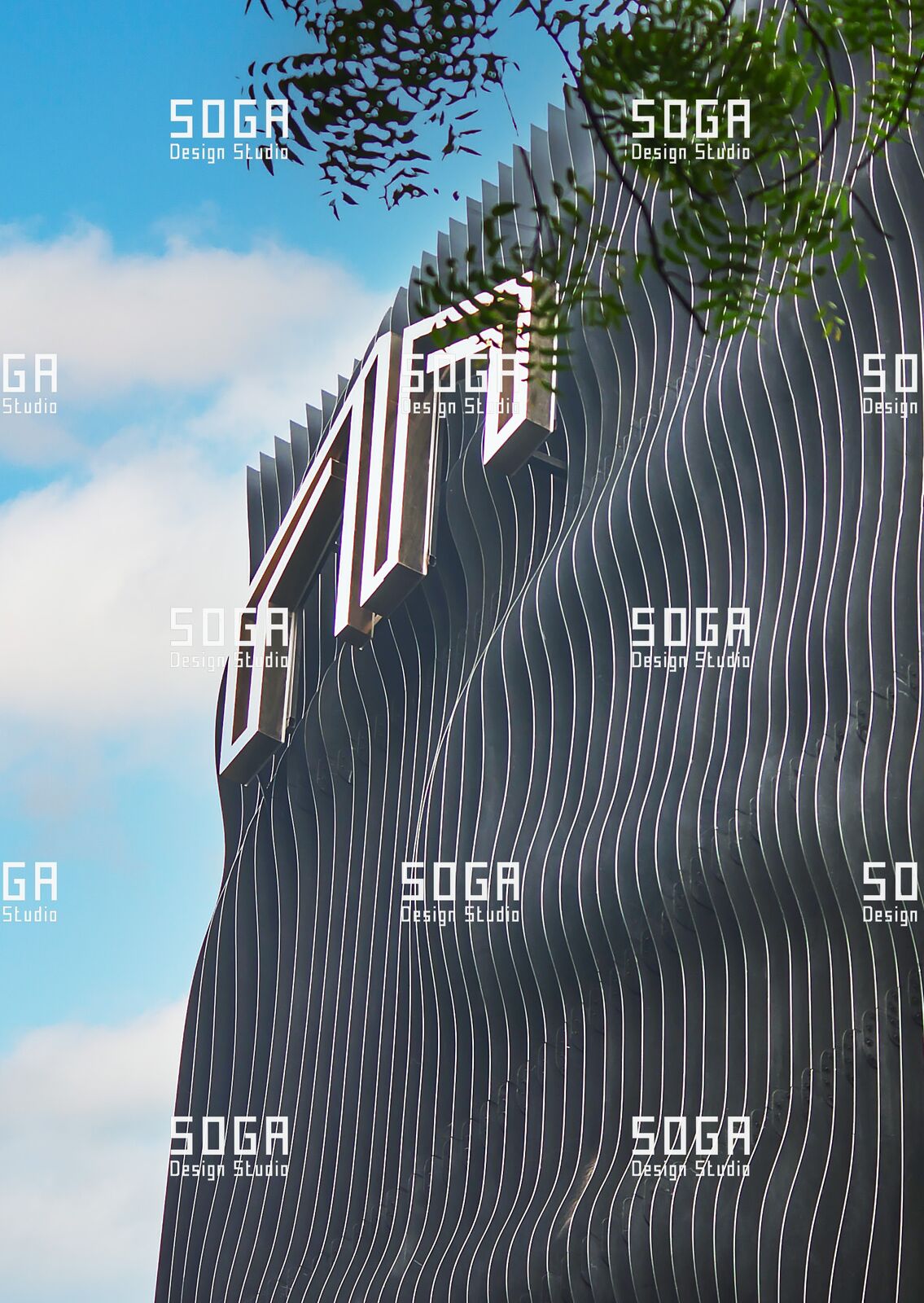
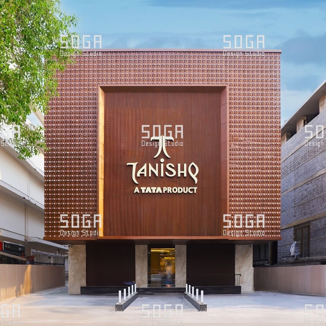
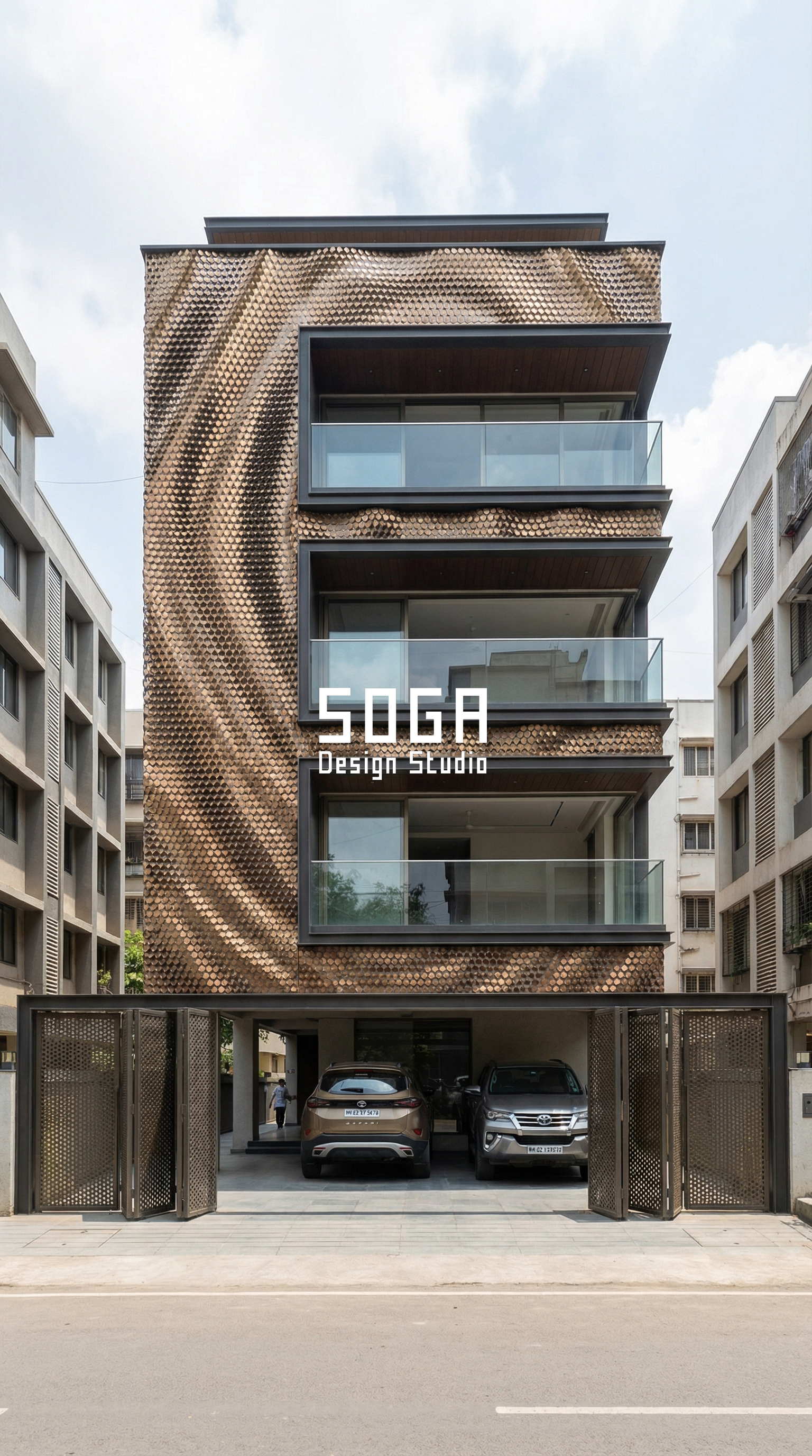
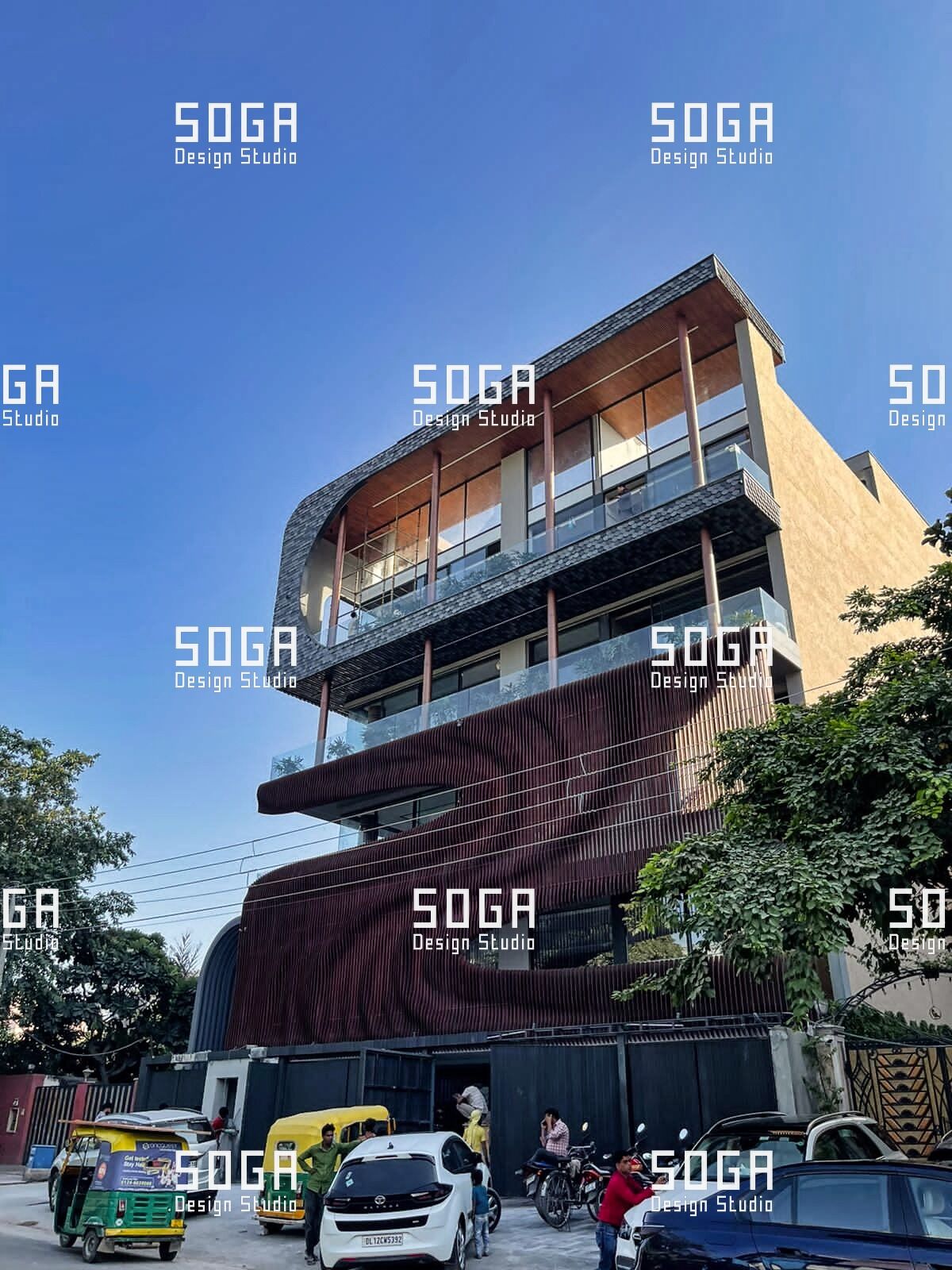
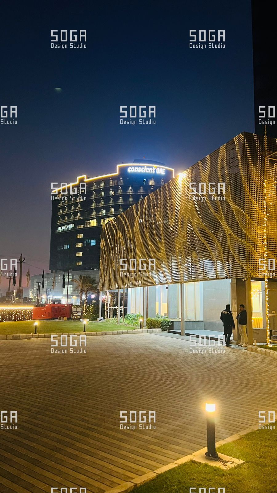
These are concept designs by SOGA Design Studio, produced as design visualisations rather than photographs of completed buildings.
How wide should a facade panel joint be?
For a dark-finished aluminium rainscreen in north India, an open drained panel-to-panel joint needs 6 mm nominal up to 1.5 m panel length, 8 mm at 1.8 m, 9 mm at 3 m, 12 mm at 4.5 m and 14 mm at 6 m. Every one of those numbers assumes a 3 mm clear gap still survives at peak surface temperature.
There is no house-style joint width, and any fabricator who has been handed a drawing marked “joint 10 mm typ.” across every module on the elevation has been handed a guess. The joint is a budget with four entries: the thermal closure of the panel, the fabrication tolerance on the panel length, the setting-out tolerance of whatever the panel is hung from, and the residual clear gap that has to remain when everything has moved the wrong way at once. Change any one of those and the number changes. Change the panel from 1.2 m to 6 m and the number more than doubles.
The residual is the only entry that is non-negotiable. Below roughly 3 mm the two panel edges are close enough that a fixing which has drifted, a burr on a folded return, or a panel that came out 1.5 mm long will put them into contact. Once they bear, the thermal load stops being a movement and becomes a force, and that force goes straight into the fixings. That is the whole reason the arithmetic is done before the first sheet is cut rather than after the first summer.
| Panel length (long dimension) | Open drained joint, nominal | Sealed joint, nominal | Governing input |
|---|---|---|---|
| Up to 900 mm | 6 mm | 8 mm | Tolerance, not movement |
| 901 – 1,500 mm | 6 mm | 8 mm | Tolerance, not movement |
| 1,501 – 1,800 mm | 8 mm | 10 mm | Balanced |
| 1,801 – 3,000 mm | 9 mm | 14 mm | Thermal movement |
| 3,001 – 4,500 mm | 12 mm | 21 mm | Thermal movement |
| 4,501 – 6,000 mm | 14 mm | 27 mm | Thermal movement – break the module instead |
Those are the figures for a dark anodised or dark PVDF finish in Delhi, Jaipur or Chandigarh, where a sun-facing panel sees the widest surface temperature range in the country. A light finish on the same elevation, or a coastal southern city, drops most modules by one band. The method for getting from a climate to a joint is identical everywhere, and it is the same method behind every other dimension in a parametric facade package: the number is derived, then drawn, then checked on site.
What actually sets a facade panel joint width?
Five inputs set it. Two of them are deterministic and pull in one direction only; three are random and can pull either way. Treating all five the same way is the most common detailing error on a panel schedule, and it produces either a joint that closes hard in May or a joint so wide the elevation reads as a stack of loose parts.
- Thermal closure of the panel – deterministic, one direction. On a 3 m aluminium panel at a 55 K heating swing this is 3.80 mm.
- Fabrication tolerance on panel length – random, both directions. Budget ±1.0 mm up to 1.5 m, ±1.5 mm to 3 m, ±2.0 mm to 4.5 m, ±2.5 mm to 6 m.
- Setting-out tolerance of the supporting line – random, both directions. Budget ±1.0 mm per module on a surveyed and shimmed substructure, ±1.5 mm on modules over 1.5 m.
- Building movement – deterministic per event, both directions. Storey drift and slab deflection, both code-limited and both covered further down.
- Residual clear gap – a fixed minimum you choose. 3 mm for an open drained joint; more if the joint also has to drain, ventilate or receive a baffle.
The way they combine matters as much as their values. Add the deterministic terms arithmetically, because they genuinely all happen on the same afternoon. Combine the random terms as a root-sum-square, because a panel that is 1.5 mm long meeting a setting-out line that is 1.5 mm tight at the same joint is a coincidence, not a design case: √(1.5² + 1.5²) = 2.12 mm, not 3.0 mm. If you add everything arithmetically you will specify a 20 mm joint on a 3 m panel and the architect will delete it. If you root-sum-square the thermal term as well, you will under-size it and the panels will meet.
So the working formula for the nominal joint is W = residual + thermal closure + √(fabrication² + setting-out²), rounded up to the next whole millimetre and then checked in both directions. The check that matters structurally is the minimum at peak surface temperature, which must never fall below the residual you chose. The check the client will notice is the maximum on the coldest night, which is the widest that shadow line will ever look.
Which coefficient of thermal expansion applies, and how do you calculate the movement?
Free thermal movement is ΔL = α × L × ΔT, where α is the coefficient of linear thermal expansion in per °C, L is the panel length in millimetres and ΔT is the temperature change in kelvin. For a 3,000 mm aluminium panel heated 55 K above its installation temperature: 23 × 10⁻⁶ × 3,000 × 55 = 3.80 mm.
The L in that equation is the panel length, not the building length and not the run length. A correctly detailed panel has one fixed connection and lets everything else slide, so it grows outward from that point. Where the fixed point sits at the panel centre, each half grows by α × (L/2) × ΔT and the joint between two neighbouring panels closes by the sum of the two adjacent halves, which comes to exactly one panel’s worth of movement. Where the fixed point sits at one end, that panel’s whole growth lands on one joint and none on the other. Either way the joint closure equals α × L × ΔT for one module. That equivalence is worth knowing, because it means you can size the joint before you have decided where the fixed point goes.
| Material | α (×10⁻⁶ per °C) | Movement per metre per 50 K | Open joint at 1.2 m panel | Open joint at 3.0 m panel |
|---|---|---|---|---|
| Aluminium composite panel (core-bonded) | 24.0 | 1.20 mm | 6 mm | 10 mm |
| Aluminium 5052 / 6063 | 23.0 | 1.15 mm | 6 mm | 9 mm |
| Titanium zinc, with the rolling grain | 22.0 | 1.10 mm | 6 mm | 9 mm |
| Brass (CuZn) | 19.0 | 0.95 mm | 6 mm | 9 mm |
| Stainless steel 304 (austenitic) | 17.0 | 0.85 mm | 6 mm | 8 mm |
| Copper | 16.5 | 0.83 mm | 6 mm | 8 mm |
| Mild steel and weather-resistant steel | 12.0 | 0.60 mm | 6 mm | 8 mm |
| Glass-reinforced concrete (GRC) | 12.0 | 0.60 mm | 6 mm | 8 mm |
| Stainless steel 430 (ferritic) | 10.4 | 0.52 mm | 6 mm | 7 mm |
| Reinforced concrete substrate | 10.0 | 0.50 mm | – | – |
| Float glass | 9.0 | 0.45 mm | – | – |
| Fired terracotta | 5.5 | 0.28 mm | 5 mm | 7 mm |
Read that table twice. At 1.2 m the entire material column collapses to the same 6 mm answer, because at short module lengths thermal movement is not the governing input at all – fabrication and setting-out tolerance are. At 3.0 m the materials separate by 3 mm from terracotta to composite, and the coefficient starts doing real work. The practical rule: below about 1.5 m of panel length, argue about tolerance; above about 2 m, argue about temperature.
Two materials do not behave the way the table suggests. Aluminium composite panel follows aluminium at roughly 24 × 10⁻⁶ in the plane of the sheet, but its two skins sit either side of a core and can reach different temperatures – a hot outer face against a cooler inner face bows the panel out of plane, which is a different problem from joint closure and is why composite panel edges are returned and stiffened rather than left as a raw cut. Fired terracotta has the lowest coefficient in the table but also carries a slow, irreversible moisture expansion after firing; carry an additional allowance on long terracotta runs and confirm the figure with the extruder rather than assuming the thermal number is the whole story.

Why you use surface temperature, not shade air temperature
A facade panel is not at air temperature. A dark metal panel in direct sun sits roughly 40 K above the shade air temperature, so a 45 °C Delhi afternoon puts the panel at about 85 °C. Sizing a joint from the weather report instead of the panel surface under-sizes it by close to half.
The estimate is simple enough to do on the drawing. Surface temperature rise above air is approximately (solar absorptance × irradiance) ÷ surface heat transfer coefficient. Take a peak vertical irradiance of 900 W/m² and a combined outdoor surface coefficient of 20 W/m²·K, which is a reasonable working value for a vertical facade in light wind. A dark graphite or dark bronze finish with an absorptance of 0.90 gives 0.90 × 900 ÷ 20 = 40.5 K above air. An off-white or light champagne finish at 0.30 gives 13.5 K. That 27 K difference between a dark and a light finish on the same building is worth 1.9 mm of closure on a 3 m aluminium panel, which is why a finish change late in a project is a joint question and not only a colour question.
The cold end matters just as much and gets forgotten because nobody photographs a facade in January. On a clear winter night a facade radiates to the sky and sits a few kelvin below air temperature. A Delhi minimum of 4 °C air puts the panel at about 0 °C. Against an 85 °C summer surface that is an 85 K total range on the same piece of metal, and both ends of it are real.
| Region | Design min surface | Design max surface, dark finish | Total range, dark | Heating swing from 30 °C install | Total range, light finish |
|---|---|---|---|---|---|
| Delhi / Jaipur / Chandigarh | 0 °C | 85.5 °C | 85.5 K | +55.5 K | 58.5 K |
| Ahmedabad / Nagpur | 7 °C | 84.5 °C | 77.5 K | +54.5 K | 50.5 K |
| Bengaluru / Hyderabad | 10 °C | 78.5 °C | 68.5 K | +48.5 K | 41.5 K |
| Mumbai / Pune | 11 °C | 76.5 °C | 65.5 K | +46.5 K | 38.5 K |
| Chennai / Kochi | 15 °C | 80.5 °C | 65.5 K | +50.5 K | 38.5 K |
| Dubai / Abu Dhabi / Doha | 6 °C | 88.5 °C | 82.5 K | +58.5 K | 55.5 K |
| Singapore / Kuala Lumpur | 19 °C | 74.5 °C | 55.5 K | +44.5 K | 28.5 K |
The fourth column is the one that pays. Note that Singapore, which never gets cold, has a smaller design range than Delhi despite similar daytime peaks, and that Dubai carries the largest heating swing of any of them. Note also the installation temperature assumption of 30 °C. That is a choice, and it belongs on the drawing. A panel field erected in a Delhi January at 12 °C surface starts near its shortest, and every joint set to nominal that day will be tighter than nominal for the rest of the building’s life. Where the programme forces cold-weather or peak-summer installation, the setting-out gap is adjusted for the day and the adjusted figure is issued as a site instruction, rather than left to the fixers to work out on the scaffold.
What do fabrication and installation tolerance add?
On a folded aluminium cassette the fabrication tolerance on the finished long dimension is the accumulation of the sheet cut, the brake setback at each fold, and the assembly of the corner. A well-run shop holds ±1.0 mm on a panel up to 1.5 m without special measures. Past 3 m the sheet itself starts to matter – thermal growth of the blank on a hot shop floor, springback variation along a long fold, cumulative setback error over four folds – and ±1.5 mm is the honest figure. At 6 m it is ±2.5 mm. A shop quoting ±0.5 mm at 6 m is quoting the laser, not the finished part.
Installation tolerance is spent on the wall. Even with a surveyed substructure, a shimmed carrier and a laser line, a fixer positioning a module against a gridline will land within about ±1.0 mm on a module up to 1.5 m and ±1.5 mm above that. That is not sloppiness; it is the resolution of the operation. What matters is that the error stays random and does not accumulate, which is a setting-out decision covered further down.
Combined for a 3 m module: √(1.5² + 1.5²) = 2.12 mm. Add that to 3.80 mm of thermal closure and a 3 mm residual and you get 8.92 mm, which is why the answer is 9 mm and not “10 mm typ.” The 1.08 mm you saved is not the point. The point is that when site asks whether 8 mm will do, you can answer in numbers instead of in opinions.
Where a panel is formed rather than folded – pressed relief, drawn discs, roll-formed bands – the tolerance comes from the tooling and the springback of the specific alloy and temper, not from the brake. Both routes are set out in more detail in our notes on folding, depth tolerance and rigidity in block panels and on blanking, forming and finishing a disc-based system. Whichever route the part takes, the number that goes into the joint calculation is the measured tolerance from a first-article check, not the number in the brochure.
Worked joint widths for aluminium panels from 600 mm to 6 m
The table below is the full working for a dark aluminium rainscreen panel in north India. The assumptions, all of which belong on the drawing: α = 23 × 10⁻⁶ /°C, installation at 30 °C surface, heating swing +55 K, cooling swing −30 K, residual clear gap 3 mm at peak temperature, and fabrication and setting-out tolerances as tabled above, combined as a root-sum-square.
| Panel length | Thermal closure at +55 K | Fab. tol. | Setting-out tol. | Combined random (RSS) | Calculated W | Specified W | Gap at 85 °C | Gap at 0 °C |
|---|---|---|---|---|---|---|---|---|
| 600 mm | 0.76 mm | ±1.0 | ±1.0 | 1.41 mm | 5.17 mm | 6 mm | 3.8 mm | 7.8 mm |
| 900 mm | 1.14 mm | ±1.0 | ±1.0 | 1.41 mm | 5.55 mm | 6 mm | 3.5 mm | 8.0 mm |
| 1,200 mm | 1.52 mm | ±1.0 | ±1.0 | 1.41 mm | 5.93 mm | 6 mm | 3.1 mm | 8.2 mm |
| 1,500 mm | 1.90 mm | ±1.0 | ±1.0 | 1.41 mm | 6.31 mm | 7 mm | 3.7 mm | 9.5 mm |
| 1,800 mm | 2.28 mm | ±1.5 | ±1.5 | 2.12 mm | 7.40 mm | 8 mm | 3.6 mm | 11.4 mm |
| 2,400 mm | 3.04 mm | ±1.5 | ±1.5 | 2.12 mm | 8.16 mm | 9 mm | 3.8 mm | 12.8 mm |
| 3,000 mm | 3.80 mm | ±1.5 | ±1.5 | 2.12 mm | 8.92 mm | 9 mm | 3.1 mm | 13.2 mm |
| 4,500 mm | 5.69 mm | ±2.0 | ±1.5 | 2.50 mm | 11.19 mm | 12 mm | 3.8 mm | 17.6 mm |
| 6,000 mm | 7.59 mm | ±2.5 | ±1.5 | 2.92 mm | 13.51 mm | 14 mm | 3.5 mm | 21.1 mm |
The last two columns are the ones to put in front of an architect. At 1.2 m the visible gap lives between 3.1 mm and 8.2 mm across the year – a shadow line that changes, but stays a shadow line. At 6 m it lives between 3.5 mm and 21.1 mm. Twenty-one millimetres is not a shadow gap; it is an opening, with a clear view of the carrier system behind it. Nothing in that row is wrong and the calculation is still correct – it is simply the arithmetic telling you that 6 m was the wrong module.
Which makes module length a joint decision before it is a handling decision. The usual reasons for choosing a module – sheet yield, crane capacity, what fits on a lorry to site, how many people it takes to lift – are all real, and they all sit downstream of this. If the elevation wants a 6 m read, it is generally cheaper and always calmer to run three 2 m modules with 9 mm joints and align them dead-on, than to run one 6 m module with a 14 mm joint at each end.
Why an 8 mm joint that works at 1.2 m fails at 6 m
Take a single “8 mm typical” note and apply it down the panel schedule. At 1.2 m it leaves 5.07 mm of clear gap at peak temperature, which is comfortable. At 4.5 m it leaves −0.19 mm. At 6 m it leaves −2.51 mm. A negative residual is not a tight joint; it is two panels pushing.
- 1,200 mm panel: 8 − 1.52 closure − 1.41 random = 5.07 mm clear. Correct, if slightly generous.
- 1,800 mm panel: 8 − 2.28 − 2.12 = 3.60 mm clear. Correct.
- 2,400 mm panel: 8 − 3.04 − 2.12 = 2.84 mm clear. Marginal – already below the 3 mm residual.
- 3,000 mm panel: 8 − 3.80 − 2.12 = 2.08 mm clear. Under-sized.
- 4,500 mm panel: 8 − 5.69 − 2.50 = −0.19 mm. The panels meet.
- 6,000 mm panel: 8 − 7.59 − 2.92 = −2.51 mm. The panels have been fighting since the first hot week.
What happens next is worth spelling out, because it is not dramatic and that is exactly why it goes unnoticed. When two panels bear, the expansion that had nowhere to go turns into a compressive force and the softest element in the chain gives way. Usually that is the folded return at the panel edge, which buckles locally by a fraction of a millimetre; sometimes it is the fixing, which elongates its own hole. Either way the deformation is permanent. The following winter the joint measures wider than nominal, because the assembly has taken up the difference plastically, and by the third summer the line has visibly stepped. Nobody on site connects the two events.
If a panel were fully restrained at both ends and could not move at all, the stress in it would be σ = E × α × ΔT. For aluminium at a 55 K rise: 70,000 MPa × 23 × 10⁻⁶ × 55 = 88.6 MPa. For mild steel at the same rise it is 132 MPa, and for stainless 304 it is 180 MPa. The aluminium figure is well below the proof stress of 5052-H32, so the metal is not yielding in tension terms – but a 2 to 3 mm sheet in a cassette buckles out of plane at a small fraction of that stress. The panel does not break. It bulges, quietly, and stays bulged.

Open drained joint or sealed joint – what does each demand?
An open drained joint is a clear air gap between panels, with the weather line held on a drained and ventilated cavity behind. A sealed joint closes that gap with a sealant bead, making the joint itself the weather line. Both are correct details. They demand completely different joint widths and completely different maintenance.
| Open drained joint | Sealed joint | |
|---|---|---|
| Weather line | Behind the panel, on the drainage cavity | The joint itself |
| Typical width, 1.2 m aluminium panel | 6 mm | 8 mm |
| Typical width, 3.0 m aluminium panel | 9 mm | 14 mm |
| Typical width, 6.0 m aluminium panel | 14 mm | 27 mm |
| What controls the width | Residual gap + movement + tolerance | Sealant movement capability – roughly twice the movement range |
| Behind the joint | Baffle or open drainage path, ventilated cavity | Backer rod and bond breaker, closed |
| Visual reading | Deep dark shadow line | A coloured line the width of the bead |
| Tolerance forgiveness | Higher – a 1 mm variation is just a 1 mm variation | Lower – variation changes bead geometry and its movement capacity |
| Maintenance cycle | Inspect cavity and drainage path; no consumable in the joint | Cut out and replace the bead, typically at 10-15 years |
| Fails by | Blocked drainage path; wind-driven water past a missing baffle | Adhesion or cohesion failure of the bead, then water in the cavity |
| Suits | Rainscreen, deep-relief and formed systems, long modules | Shallow modules, wet-sealed stone and composite panels, short runs |
For anything a fabricator would recognise as a rainscreen – block panels, formed relief modules, disc fields, fin systems – the open drained joint is almost always the right answer, and the reason is in the table: at 3 m it saves 5 mm of visible joint width and it removes a consumable from the elevation. The cavity behind then has to be detailed properly, which means a real drainage path, a real ventilation opening area, and dissimilar-metal separation wherever the carrier and the panel are different alloys. That last point is a corrosion question rather than a movement one, and it is covered in our guide to whether metal facades rust in India.
Cost sits differently on the two as well. On the same elevation, the difference between an open drained joint with a baffle and a wet-sealed joint typically falls in the range of Rs 90 to Rs 240 per running metre of joint in material and labour, before you price the re-sealing cycle at year 10 to 15. Both figures move with access, height and sealant grade, and SOGA issues an itemised estimate per project rather than a single rate.

How wide does a sealed joint have to be?
A sealed joint is sized by the movement capability of the sealant, not by the movement of the panel. A class 25 sealant accommodates ±25% of the installed joint width, so it absorbs a total range of 50% of that width. The joint must therefore be at least twice the total movement range, with tolerance added on top.
The total movement range is the full swing, not the heating swing: α × L × 85 K for the north Indian dark-finish case. On a 3 m aluminium panel that is 5.87 mm, so the sealant needs 11.73 mm before tolerance and 13.85 mm after, which specifies at 14 mm. ISO 11600 sets the movement classes, and the class you specify moves the answer a very long way.
| Panel length | Total movement range (85 K) | Width needed, class 12.5E | Class 20 LM | Class 25 LM | Class 35 |
|---|---|---|---|---|---|
| 1,200 mm | 2.35 mm | 19 mm | 12 mm | 9 mm | 7 mm |
| 1,800 mm | 3.52 mm | 28 mm | 18 mm | 14 mm | 10 mm |
| 2,400 mm | 4.69 mm | 38 mm | 23 mm | 19 mm | 13 mm |
| 3,000 mm | 5.87 mm | 47 mm | 29 mm | 23 mm | 17 mm |
| 4,500 mm | 8.80 mm | 70 mm | 44 mm | 35 mm | 25 mm |
| 6,000 mm | 11.73 mm | 94 mm | 59 mm | 47 mm | 34 mm |
Those are the widths from movement capability alone, before tolerance and before the practical minimum. They are shown raw deliberately, because the pattern is the lesson: a cheap class 12.5 sealant on a 3 m dark aluminium panel would need a 47 mm joint to survive, which nobody is going to draw. So what actually gets built is a 12 mm joint with a class 12.5 bead in it, and it fails in adhesion within four or five summers. If the joint is sealed, the sealant class is a load-bearing decision and belongs in the specification with the same weight as the alloy.
Three geometry rules go with it, and they are the ones most often lost between specification and site. Width to depth is 2:1 for a movement joint, so a 14 mm joint gets a 7 mm bead depth, controlled with a closed-cell backer rod. The bead must adhere to two faces only – a bond breaker at the back is what lets it stretch, and three-sided adhesion tears it. And the minimum practical width for any movement bead is 6 mm regardless of what the arithmetic says, because below that you cannot tool it and you cannot get a backer rod into it.
Where does a movement break go in a long continuous run?
Panels are short. The things that run long are copings, continuous fins, edge trims, carrier rails and bands, and they are where thermal movement actually causes trouble. A continuous element gets one fixed point, slotted connections everywhere else, and a designed movement break before the accumulated travel exceeds what the slot allows.
The spacing follows from the slot. If a slotted connection offers ±5 mm of travel and the element grows outward from its fixed point in both directions, each side can run 5 ÷ (23 × 10⁻⁶ × 55) = 3,953 mm, so the total run between breaks is about 7.9 m.
| Travel available at the connection | Free length each side of the fixed point | Maximum run between movement breaks | Practical spacing to specify |
|---|---|---|---|
| ±3 mm | 2,372 mm | 4,743 mm | 4.5 m |
| ±4 mm | 3,162 mm | 6,324 mm | 6.0 m |
| ±5 mm | 3,953 mm | 7,905 mm | 7.5 m |
| ±6 mm | 4,743 mm | 9,486 mm | 9.0 m |
| ±8 mm | 6,324 mm | 12,648 mm | 12.0 m |
| ±10 mm | 7,905 mm | 15,810 mm | 15.0 m |
Two things go wrong with this in practice. The first is that a fabricator, wanting a clean line, fixes a long element at both ends with plain round holes because slotted holes look untidy on a drawing – and then the element has nowhere to go. The second is that the slot exists but is filled: a washer torqued down hard onto a slot is a fixed point, whatever the drawing says. Slotted connections in a movement run get a shouldered fastener or a controlled clamping load, and that note has to sit on the fabrication drawing, not in a specification clause nobody opens.
Where the break lands is a design decision, not a convenience. Put it on a line the elevation already has – a floor line, a bay division, the edge of a change in module – so it reads as intentional rather than as a repair. On systems built from many small units the break can be absorbed within the field itself, which is one of the quiet advantages of a small-module approach; the scale-based cladding system handles thermal movement across a field of many small overlapping units rather than at a handful of large joints.
What does building movement add to the joint?
Two structural movements land on a panel joint and neither of them is thermal. Storey drift racks the facade sideways and is taken by the vertical joints; slab deflection drops the floor edge and is taken by the horizontal joint at that floor line. Both are code-limited, so both give you a number to work with.
IS 1893 (Part 1):2016 limits storey drift under design lateral load to 0.004 times the storey height. On a 3.2 m storey that is 12.8 mm of relative horizontal movement between one floor and the next. It is not distributed evenly to every joint on the elevation – it is an in-plane shear across the panel field within that storey – but if a bay carries four vertical joints across it, each is being asked to accept of the order of 3.2 mm of relative in-plane movement without the panel corners grinding on each other.
IS 456:2000 limits deflection occurring after the construction of partitions and finishes to span/350 or 20 mm, whichever is less. A 6 m slab span gives 17.1 mm; a 7 m span reaches the full 20 mm cap. That is the movement a horizontal joint at the floor line has to swallow, and it dwarfs anything thermal on the same elevation.
| Movement source | Code basis | Input | Movement to accommodate | Which joint takes it |
|---|---|---|---|---|
| Storey drift | IS 1893 (Part 1):2016, 0.004h | 3.0 m storey | 12.0 mm | Vertical joints, in-plane |
| Storey drift | IS 1893 (Part 1):2016, 0.004h | 3.2 m storey | 12.8 mm | Vertical joints, in-plane |
| Storey drift | IS 1893 (Part 1):2016, 0.004h | 3.6 m storey | 14.4 mm | Vertical joints, in-plane |
| Storey drift | IS 1893 (Part 1):2016, 0.004h | 4.0 m storey | 16.0 mm | Vertical joints, in-plane |
| Slab deflection after finishes | IS 456:2000, span/350 or 20 mm | 4 m span | 11.4 mm | Horizontal joint at floor line |
| Slab deflection after finishes | IS 456:2000, span/350 or 20 mm | 6 m span | 17.1 mm | Horizontal joint at floor line |
| Slab deflection after finishes | IS 456:2000, span/350 or 20 mm | 7 m span | 20.0 mm | Horizontal joint at floor line |
| Slab deflection after finishes | IS 456:2000, span/350 or 20 mm | 8 m span | 20.0 mm (capped) | Horizontal joint at floor line |
This is why a well-detailed elevation frequently carries two joint widths rather than one: a 9 mm vertical joint through the field and a 15 to 20 mm horizontal joint at the floor line, the wider one shadowed, recessed or expressed as a band so the difference reads as a designed line instead of an inconsistency. Trying to run one width everywhere means either the field joints are absurdly wide, or the floor-line joint closes when the slab takes its long-term deflection.
One note on which edition of the Indian code you are working to, because it changed this year. SP 7:2026, the National Building Construction Standards, was published on 30 April 2026 and the National Building Code of India 2016 (SP 7:2016) was withdrawn on the same date. The Bureau of Indian Standards foreword to the new edition records the rename from National Building Code to National Building Construction Standards. If a specification on your desk still calls up SP 7:2016, it is calling up a withdrawn document. The two limits used above come from separate standards – IS 1893 (Part 1):2016 for drift and IS 456:2000 for deflection – and are cited here on their own authority; where you need the equivalent provision inside the new edition, confirm the Part against a current BIS copy rather than carrying a Part number across from the old structure.
How the panel is held while all this happens – the bracket, the anchor into the concrete, the slotted hole, the shim – is a separate interface with its own failure modes, and it is not the subject here. This post is about the visible dimensional gap between two panels. The two problems are solved on different drawings, and confusing them is how a movement allowance ends up drawn twice, or not at all.
How do you stop the shadow gap wandering across the elevation?
A joint that measures correctly and still looks wrong is a setting-out failure. The rule SOGA works to is ±1 mm between any two adjacent joints and ±2 mm across any ten-module run. The eye reads relative difference, not absolute width, so a consistent 10 mm joint always looks better than one that is sometimes 8 and sometimes 9.
Whether you can hold that depends entirely on how the field is set out. Chain the modules – set each one off its neighbour, which is what happens naturally when a fixer works along a run – and the ±1 mm per module accumulates. Set every module against an absolute datum taken from the survey grid, and the error never accumulates at all.
| Modules in the run | Error if chained module-to-module (worst case) | Error if chained (statistical, RSS) | Error if set from an absolute datum |
|---|---|---|---|
| 5 | 5.0 mm | 2.24 mm | 1.0 mm |
| 10 | 10.0 mm | 3.16 mm | 1.0 mm |
| 20 | 20.0 mm | 4.47 mm | 1.0 mm |
| 40 | 40.0 mm | 6.32 mm | 1.0 mm |
Twenty chained modules can put the last joint 20 mm out of position, and even the statistical figure of 4.47 mm is more than four times the visual rule. The fix is not a better fixer; it is a setting-out method. Mark the absolute position of every module edge onto the substructure from the grid before the first panel goes up, or mark a reset line at every fifth module so accumulation can never exceed five modules’ worth. On a formed-module field those reset lines also give you the check points for the alignment sweep before the access equipment comes down – the same discipline that keeps a depth-based block panel field reading as one surface rather than as a set of separate runs.
When the building itself is out of true – and on an RCC frame it will be – the error goes into the substructure, never into the visible joint. The packing behind the panel absorbs the deviation and the face line stays true. That means the substructure needs a real adjustment range designed into it from the start, and it means the survey has to happen before the panel schedule is frozen, not after the panels have reached the paint line.
What actually goes wrong, and what each failure looks like
Five failure modes cover almost everything that goes wrong at a panel joint. Each has a distinct signature on the elevation and each traces back to a specific line in the arithmetic above. Knowing the signature lets you diagnose from a photograph before anyone puts up a cradle.
| Failure | What you see | Root cause in the calculation | The number that would have caught it |
|---|---|---|---|
| Panel buckling | A localised bulge or dish in the panel face, worst in the afternoon, permanent by the second summer | Residual gap went negative; the panel is effectively restrained at both ends | σ = EαΔT = 88.6 MPa in aluminium at 55 K; a 2 mm sheet buckles far below this |
| Joint closing in summer | The shadow line disappears on the sun-facing elevation and returns in winter | Joint sized on shade air temperature instead of surface temperature | 40.5 K surface rise on a 0.90-absorptance finish at 900 W/m² |
| Wandering shadow line | Joints visibly wider at one end of a run; the line kinks at a floor level | Modules chained off each other instead of set from an absolute datum | 20 chained modules at ±1 mm = 20 mm worst case, 4.47 mm RSS |
| Sealant adhesion failure | The bead pulls away from one face; staining below the joint within four or five summers | Joint narrower than twice the movement range, or the wrong sealant class specified | Class 25 accommodates 50% of width; a 3 m aluminium panel moves 5.87 mm and needs 14 mm |
| Edge fretting and noise | A tick or a crack heard from the elevation as the sun moves onto it | Panel sliding under load against an unlined bearing surface | 3.80 mm of travel per 3 m module, cycled every day of the building’s life |
The last one is the least discussed and the most complained about. A panel that is correctly free to move has to move against something, and metal sliding on metal under load makes noise. Isolation tape, a low-friction pad or a nylon washer at the sliding connection costs almost nothing at fabrication and is close to impossible to retrofit at the twentieth floor. Specify it alongside the joint, in the same schedule.
The honest limit on all of this: every figure in this post is a design calculation from stated assumptions, not a measurement of your building. Solar absorptance varies with the actual finish and its supplier, the surface heat transfer coefficient varies with exposure and wind, and the installation temperature is whatever the programme delivers. What the method gives you is a defensible number with its assumptions written next to it, which is what a checking engineer, a main contractor and a fabricator can all argue with productively. A rule of thumb gives you nothing to argue with and no way to be right.
What must be on the drawing before anyone cuts metal
A joint width on its own is not a specification. The panel schedule and the joint schedule are issued together, and the joint schedule carries the assumptions, because in three years the person auditing a failed elevation will need to know what was assumed as much as what was drawn.
- Nominal joint width per module size, with vertical and horizontal stated separately.
- Residual clear gap at maximum temperature – the minimum the joint must never fall below.
- Coefficient of thermal expansion used, with the alloy or material grade named.
- Design maximum and minimum surface temperature, and the solar absorptance assumed for the specified finish.
- Assumed installation temperature, plus the setting-out adjustment table if erection falls outside a stated band.
- Fabrication tolerance on the panel long dimension, taken from a first-article measurement rather than a brochure.
- Setting-out tolerance per module and the datum method – absolute from grid, or the reset interval if not.
- Fixed point and sliding points marked on every panel and every continuous element.
- Movement break positions on continuous runs, with the travel available at each slotted connection.
- Joint type – open drained with baffle, or sealed with sealant class, bead depth and backer rod size.
- Storey drift and slab deflection allowances carried, with the code clause referenced.
- Isolation or low-friction material at every sliding interface.
SOGA runs this in a fixed order on every facade package: the survey before the panel schedule, the temperature and movement calculation before the joint width, the joint width before the module size is frozen, and a first-article measurement before production release. The order is not a preference. Each step consumes a number the previous step produced, and doing them out of sequence is how a project ends up with a beautiful module size and a joint that cannot be built to it.
Indicative rates for an engineered metal panel system in India, designed, fabricated and installed, sit in a broad band of roughly Rs 1,600 to Rs 4,200 per sq ft depending on material, module size, panel depth, finish system and access conditions. Joint detailing is a very small fraction of that and the single cheapest place to spend engineering time. An itemised estimate is issued per project against the actual elevation, module schedule and access conditions.
Joint width is only useful if somebody measures the joint that was actually built. See what to inspect at each stage of an elevation.
Joint width is one durability question; the coating is the other. See which facade finish actually lasts in India.
Related Reading
- Parametric facade design in India – the pillar guide
- Depth-based block panel facades: the complete guide
- How block facade panels are manufactured: folding, depth tolerance and rigidity
- How a disc-based facade is manufactured: blanking, forming, finishing and assembly
- Do metal facades rust in India? 2026 corrosion guide
- Scale-based parametric metal cladding: the complete guide
Frequently Asked Questions
How wide should a facade panel joint be?
For a dark-finished aluminium rainscreen in north India, an open drained joint needs 6 mm nominal up to 1.2 m panel length, 7 mm at 1.5 m, 8 mm at 1.8 m, 9 mm at 3 m, 12 mm at 4.5 m and 14 mm at 6 m. Every figure assumes a 3 mm clear residual gap survives at peak surface temperature, with fabrication and setting-out tolerances of plus or minus 1.0 to 2.5 mm combined as a root-sum-square rather than added arithmetically.
What coefficient of thermal expansion should I use for aluminium facade panels?
Use 23 x 10^-6 per degree C for the 5052 and 6063 alloys used in facade work, which is 1.15 mm per metre for every 50 K of surface temperature swing. Aluminium composite panel is slightly higher at about 24 x 10^-6, titanium zinc about 22 x 10^-6 with the rolling grain, copper 16.5 x 10^-6, mild steel 12 x 10^-6, stainless 304 17 x 10^-6 and fired terracotta about 5.5 x 10^-6.
Should facade expansion be calculated from air temperature or surface temperature?
Surface temperature, always. A dark metal panel with a solar absorptance around 0.90 sits about 40 K above shade air temperature at 900 watts per square metre of irradiance, so a 45 degree C Delhi afternoon puts the panel near 85 degrees C. Using shade air temperature under-sizes the joint by close to half. The design range for a dark finish in north India is roughly 0 to 85 degrees C, an 85 K total swing.
What is the difference between an open drained joint and a sealed joint?
An open drained joint is a clear air gap with the weather line held on a drained and ventilated cavity behind the panel. A sealed joint closes the gap with a sealant bead that becomes the weather line itself. On a 3 m aluminium panel the open joint is 9 mm and the sealed joint is 14 mm, because sealant width is governed by movement capability – an ISO 11600 class 25 sealant accommodates only 50 per cent of its installed width in total.
How far apart should movement breaks be in a long facade run?
It depends on the travel available at the slotted connections. With plus or minus 5 mm of travel and a 55 K heating swing, an aluminium element can run about 3,950 mm each side of its fixed point, giving roughly 7.9 m between breaks. At plus or minus 3 mm the spacing drops to about 4.5 m; at plus or minus 8 mm it extends to about 12 m. Each continuous element gets exactly one fixed point and slotted connections everywhere else.
Get the joint schedule with the panel schedule
If you are pricing or detailing a panel system and the drawing says “joint 10 mm typ.”, SOGA Design Studio will run the movement calculation against your actual module sizes, alloy, finish absorptance and city, and issue a joint schedule with the assumptions written on it – nominal width, residual gap, design surface temperatures, fixed and sliding points, and movement break positions. Send the elevation and the module grid to [email protected] and we will come back with the numbers and an itemised estimate for the package.