Hide an AC outdoor unit on a house facade with an open screen that holds its free area constant and buys privacy with depth instead of smaller holes. A 220 x 220 mm cell on a 280 mm pitch gives 62 percent free area head-on. Push member depth from 110 mm to 260 mm and that same screen goes sight-proof from the street without changing the airflow by one percent. A condenser facade screen is a fixed, open architectural screen that conceals an air-conditioner outdoor unit on a building elevation while preserving the free area the condenser needs to reject heat. Unlike a solid cover, it is sized by free-area percentage rather than by appearance, and it stands far enough off the unit to stop discharge air recirculating back into the intake. Now the part we keep getting wrong. We finish the elevation, hand it over, and let a site engineer bolt twelve condensers onto it. Then we go back and try to hide them. An outdoor unit is a facade decision that we keep taking as an MEP afterthought, and on a G+3 there are eight to twelve of them on one face. Everything below is worked five different ways, on five different streets – Nashik, Pune, Surat, Indore and Hyderabad – because the rule is not a style and does not belong to one geometry. Each of the five is a SOGA concept study, not a built project, and every dimension in them comes from manufacturer clearances, the module geometry and the plot.
Why Boxing In An AC Outdoor Unit Costs 10-15% Of The Tonnage
The MEP engineer is right to resist us, and the number is the reason. A 1.5 TR outdoor unit rejects roughly 6.8 kW of heat – the 5.3 kW it pulled out of the room plus about 1.5 kW of compressor work – through roughly 2,000 m³ of air an hour. Do the air-side sum. 2,000 m³/h is 0.67 kg/s, and at 1.005 kJ/kgK that means the discharge leaves the coil about 10 °C hotter than the air that went in. That 10 °C has to get away from the building. Every millimetre we put in front of the fan is a millimetre the fan has to push through, and on a G+3 elevation carrying twelve units that is 24,000 m³/h leaving one face. Which is exactly why the standard answers are worse than doing nothing at all. A solid timber box, a tight-slat cover, a lattice with 20 mm gaps, a hedge clipped up against the unit: every one of them recirculates discharge air back into the intake, and every 1 °C of raised condenser inlet air costs roughly 2 to 3 percent of capacity. Four to six degrees of recirculation and 10 to 15 percent of the tonnage the client paid for has quietly disappeared – along with compressor life, because a unit that cannot reject heat starts short-cycling and the condensing temperature climbs with it. The client never blames the box. They blame the air conditioner, and then they blame the architect who drew the box.
The Wada’s Third Chowk: Service Given Its Own Depth
The Deccan solved this already, and it solved it by giving service room rather than a disguise. A wada – the courtyard mansion of Nashik, Pune, Satara and Wai – is planned as two or three chowks in sequence, and in the larger houses the rear-most chowk was handed over entirely to the machinery of the household: the cattle byre (gotha), the store (kothar), the well and the wash, with its own separate entry off the lane. Nothing in that court was hidden. It was given its own depth in the plan and its own open sky above it, so it could be fed, serviced and ventilated without ever being tidied away. That is the same decision a condenser bay asks of us, moved from plan into section. The wada could spend plan depth on service; a G+3 on a 9 m frontage has no plan depth left to spend, so it spends section depth instead – a 400 mm standoff and up to 260 mm of screen in front of it. And note what the third chowk is not. It is not a light-and-privacy device sized for people. It is a machinery device sized for what the machine needs, which is the whole argument here: the equipment sets the number that cannot move, and the elevation is arranged around it afterwards.
Hold The Opening, Move The Depth – The AC Unit Screen Design Rule
Hold the opening, move the depth. Every guide on this subject, and every page currently ranking for it, assumes the only lever available is hole size – so the question always arrives framed as a trade-off. More open means more air and less privacy. Tighter means more privacy and a strangled unit. Pick your poison. That framing is the failure, and it is a failure of dimension count. Hole size is one of three dimensions. A screen also has depth, and depth does something to the eye that it does not do to the air. Air crosses a lattice perpendicular, so air only ever sees the head-on free area. A person on the street almost never stands head-on; they see the members edge-on. Fix the hole, vary the depth, and the trade-off stops existing. Our villa privacy work treats screen porosity as the privacy lever; this is the exact inverse – porosity is frozen and depth is the only thing allowed to move. Three formulae carry it, and they work on any module, not only ours. Head-on free area = cell² / pitch², which for a 220 mm cell on a 280 mm pitch is 61.7 percent, called 62. Apparent openness across the direction of view = (cell − depth × tan θ) / pitch, floored at zero. Sight-proof angle = arctan (cell / depth). Look at the first equation again: there is no depth term in it. That is the entire post in one observation. As far as the air is concerned, depth is free. Five SOGA systems below run that one rule on five unrelated geometries – member depth, cassette tilt, fin projection, blade pitch and the depth of a woven crossing – and every one of them freezes its opening and moves only in section. For the acoustic version of the same move, see reduce road noise on a house facade in India.
How Deep Should The Screen Be To Hide A Condenser?
Between 110 mm and 260 mm on the Nashik lattice, chosen bay by bay in six discrete 30 mm steps, and the cell opening never moves while you do it. The four condenser bays take 230 and 260 mm, the living-room bays take 110 mm, and the bedroom and transition bays sit between. The street sets the depth, and nothing else does. A 9 m road with a 3 m setback puts the near footpath about 12 m off the face, and the widest oblique any pedestrian gets on the condenser bays while walking the frontage is roughly 40 degrees. A 260 mm member is therefore opaque to the entire street, because it goes sight-proof at 40.2 degrees. A 110 mm member in the same elevation, with the same cell and the same pitch, is still 39 percent open at 45 degrees, so the living room behind it keeps its view out and its daylight. Three drivers set these numbers, and they set them on all five systems, not only this one: condenser free area (fixed per system – 62 percent here, 55 to 62 percent across the five, and never traded in any bay), service access (fixed at a 400 mm standoff and one demountable panel per unit, on every system), and street sightline (variable, and the only variable). Read the free-area figure down all six rows of the table. It does not move.
| Driver | What it sets, and to what |
|---|---|
| 110 mm member depth | 62% head-on free area · 39% apparent openness at 45° from the street · goes sight-proof beyond 63.4° · living-room bays, view out and daylight in |
| 140 mm member depth | 62% head-on free area · 29% apparent openness at 45° · goes sight-proof beyond 57.5° · bedroom bays |
| 170 mm member depth | 62% head-on free area · 18% apparent openness at 45° · goes sight-proof beyond 52.3° · transition bays |
| 200 mm member depth | 62% head-on free area · 7% apparent openness at 45° · goes sight-proof beyond 47.7° · service-adjacent bays |
| 230 mm member depth | 62% head-on free area · 0% apparent openness at 45° · goes sight-proof beyond 43.7° · condenser bays, lower floors |
| 260 mm member depth | 62% head-on free area · 0% apparent openness at 45° · goes sight-proof beyond 40.2° · condenser bays, upper floors and the widest street oblique |
| Cell and pitch (constant on every row) | 220 × 220 mm clear cell on a 280 mm pitch with a 60 mm member face · head-on free area = 220² / 280² = 61.7%, called 62%, unchanged at every depth |
When two drivers fight, the order is fixed and it never changes – and it is the same order on all five systems. One: the head-on free area is never traded – not for privacy, not for cost, not for a cleaner drawing. Two: vertical clearance in the stack, which is 1,000 mm minimum between units, with the 400 mm standoff cavity open at every floor. Three: member depth, or whichever quantity that system varies. Four: view. Two places on the Nashik elevation test that order, and both recur on the other four. At bay 4, second floor, the master-bedroom balcony overlaps the condenser stack: privacy asks for 260 mm and the bedroom’s street view asks for 110 mm. Depth wins, the bedroom loses, and the view moves to the side return – a decision to take at concept stage, not to discover at handover. The second is the head of the stack, where the standoff cavity wants to be closed off neatly at parapet level. Cap it and you have built a 12 m flue up the face of the building. Discharge air 10 °C hotter than ambient is buoyant, it rises inside that flue, and every unit ends up breathing the exhaust of the one below it. The cavity stays open. A tidy parapet detail is not worth 15 percent of four floors of tonnage. The same logic settles the multi-storey question on every one of the five: with eight to twelve outdoor units on a G+3, or up to eighteen on the Hyderabad G+5, put them in one continuous vertical bay line rather than scattering them room by room. Scattered units force the screen depth to jump randomly across an elevation that should read as one thing. A single stack lets one deep bay absorb every unit and leaves every other bay shallow, open and looking out.
Five Ways To Hide AC Outdoor Units On A House Facade
Five systems, five cities, five unrelated operations, and one rule underneath all of them. Each freezes its opening: the 220 mm cell and 280 mm pitch on the Nashik lattice, the 12 mm shadow gap on the Pune shingle, the 150 mm fin centres in Surat, the blade throat in Indore, the 640 mm weave pitch in Hyderabad. Each then moves exactly one quantity in the third dimension – depth, tilt, projection, blade angle, crossing depth – to buy concealment the air never pays for. Head-on free area lands between 55 and 62 percent and stays there in every bay of every one of them. That is why this is an argument and not a list: the geometries have nothing in common and they all obey the same sentence. None of the five is a built project. They are SOGA systems, drawn and costed, and the same 400 mm standoff, the same clearance table and the same service rule run through all five.
Parametric Depth Lattice
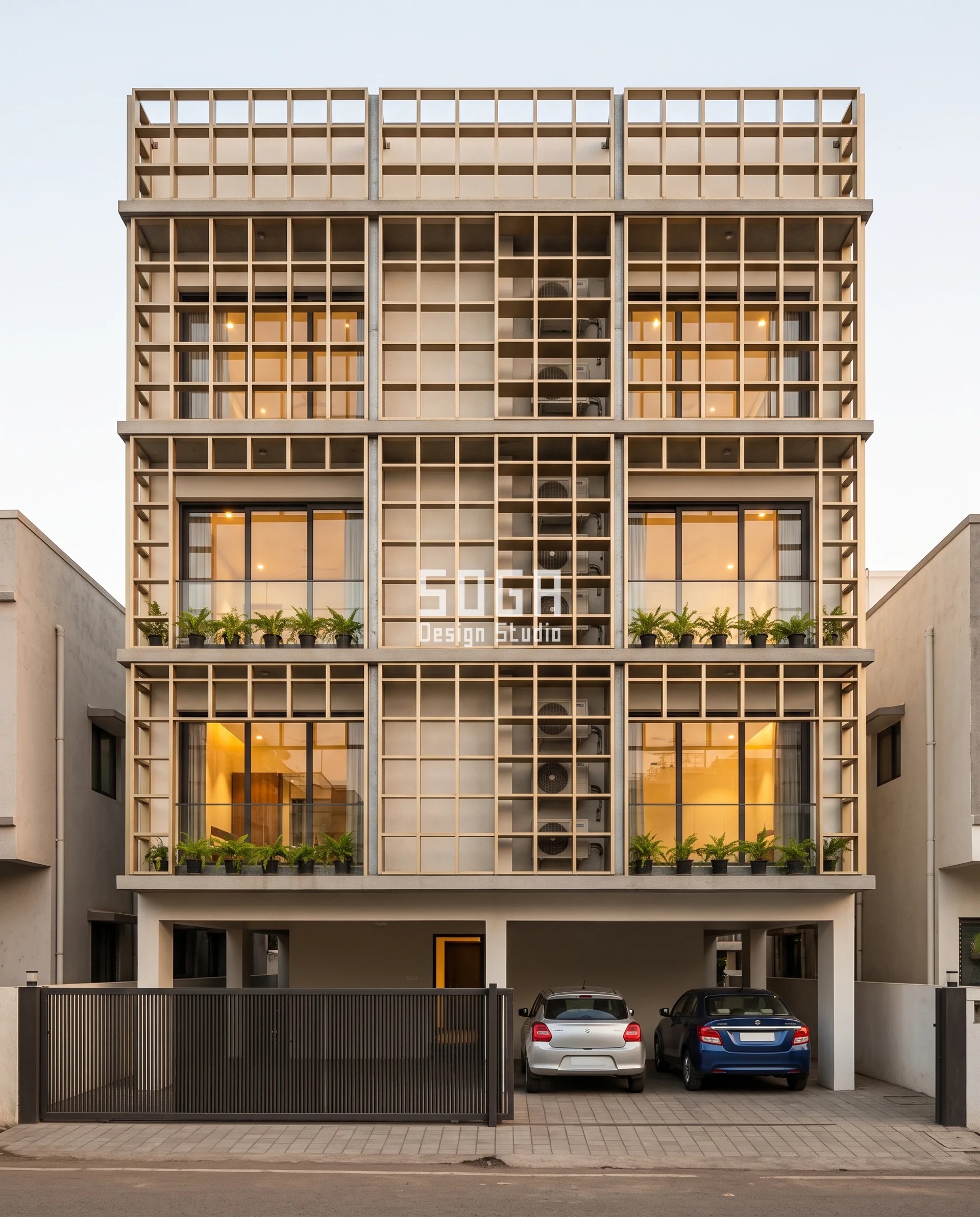
A 220 × 220 mm clear cell on a 280 mm pitch, held in every bay of a G+3 in Tidke Colony, Nashik, with only the member depth allowed to move – 110 mm at the living rooms, 260 mm at the four condenser bays, in six discrete 30 mm steps. Head-on free area reads 61.7 percent, called 62, at every one of those depths, because the formula that produces it carries no depth term. The outdoor units hang in 350 mm pockets behind the deepest bays, 400 mm clear of the backs of the members, and a 260 mm member is opaque to the whole street because it goes sight-proof at 40.2 degrees. This is the rule at its plainest: the hole never changes and the wall arrives anyway.
| Specification | Parametric Depth Lattice |
|---|---|
| Product | 60 mm face folded-metal U-channel lattice, Class AA 25-micron champagne-gold anodised, on a hot-dip galvanised MS carrier |
| Module | 1,680 × 3,080 mm welded panel, 6 × 11 cells of 220 × 220 mm clear on a 280 mm pitch, 60 mm face U-channel, 400 mm standoff |
| What varies | Member depth, 110 to 260 mm in six discrete 30 mm steps |
| Head-on free area | 62% constant, head-on, at every depth |
| Indicative rate | ₹2,900-3,700 per sq ft installed |
Parametric Tilt Shingle
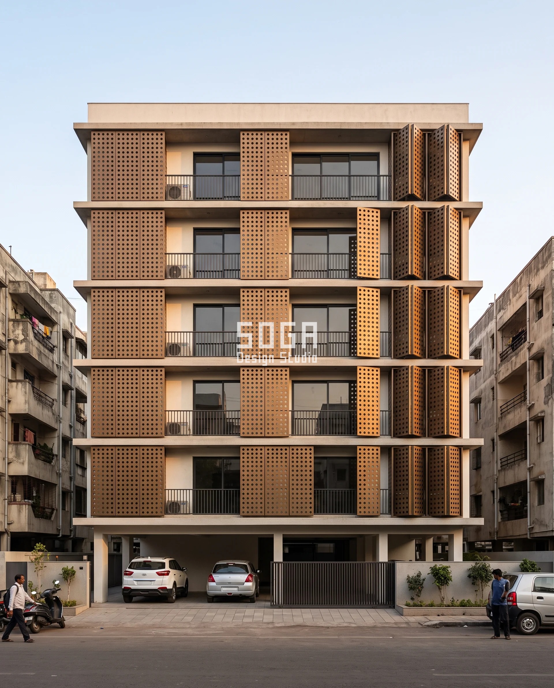
Bronze anodised cassettes, 300 mm high and 600 mm wide, punched with 40 mm round holes on 50 mm staggered centres for 58 percent open area and laid in courses with a 12 mm shadow gap that never varies anywhere on this G+4 in Kothrud, Pune. What varies is the tilt: flat across the bedrooms, stepping in five 5-degree increments to 25 degrees at the condenser stack, where the bottom edge of each cassette stands 127 mm proud of the course below. Head-on, the air crosses a single punched layer at 58 percent whatever the tilt is doing. Obliquely the eye crosses two offset layers instead – 0.58 × 0.58, or 34 percent – and at 34 percent through two misaligned hole patterns a condenser stops resolving into a shape.
| Specification | Parametric Tilt Shingle |
|---|---|
| Product | 300 × 600 mm pressed-metal cassette on a two-clip bracket, bronze anodised, 12 mm shadow gap |
| Module | 300 × 600 mm pressed-metal cassette in courses at 300 mm, 40 mm round punch on 50 mm staggered centres, 12 mm constant shadow gap, 400 mm standoff |
| What varies | Cassette tilt out of plane, 0 to 25° in five 5° steps |
| Head-on free area | 58% constant, head-on, at every tilt |
| Indicative rate | ₹2,300-2,950 per sq ft installed |
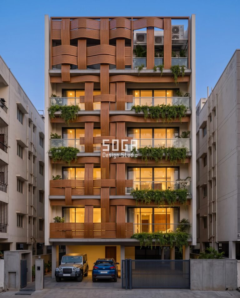
Parametric Fin Rake
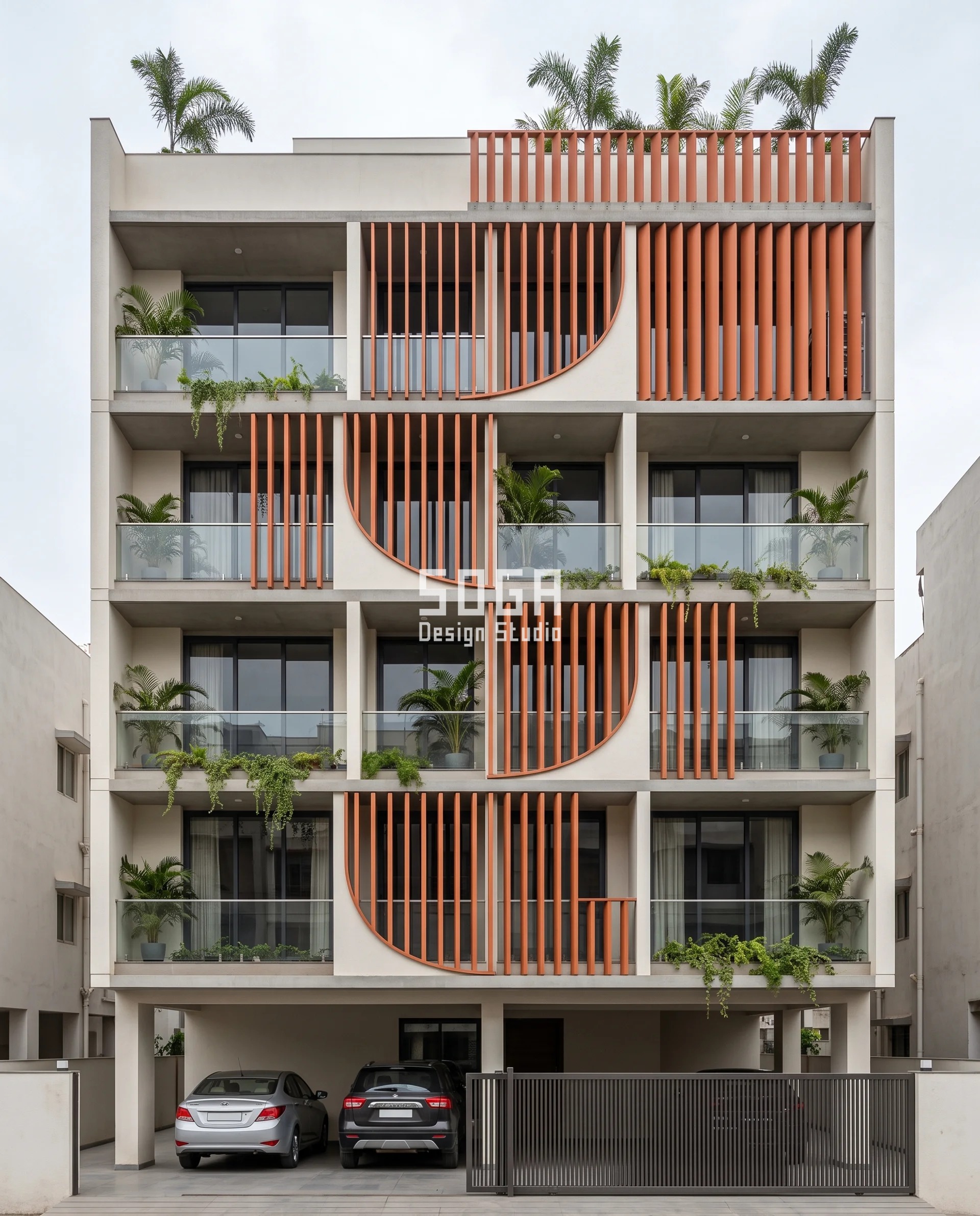
Terracotta-orange fins 60 mm wide, top-hung on a concealed rail at 150 mm centres that hold everywhere – so the clear gap is 90 mm and head-on free area is 60 percent in every bay of this G+3 in Vesu, Surat. Projection is the only variable: 90 mm at the living-room glazing, 240 mm at the condenser bays, six steps of 30 mm. A one-way fin is the most efficient of the five per millimetre of depth, because it only has to close one direction – 240 mm goes sight-proof at 20.6 degrees, where the Nashik lattice needs 260 mm to reach 40.2. That efficiency is also the honest weakness: it shuts the walk-past oblique and does nothing whatever for a neighbour looking straight in from the balcony opposite.
| Specification | Parametric Fin Rake |
|---|---|
| Product | 60 × 200 mm extruded-metal fin at 150 mm centres, terracotta-orange polyester powder coat, top-hung on a concealed rail |
| Module | 60 mm wide extruded-metal fin at constant 150 mm centres, 90 mm clear gap, projection 90-240 mm, top-hung with a free bottom, 400 mm standoff |
| What varies | Fin projection, 90 to 240 mm in six discrete 30 mm steps |
| Head-on free area | 60% constant, head-on, at every projection |
| Indicative rate | ₹2,450-3,200 per sq ft installed |
Parametric Chevron Louvre
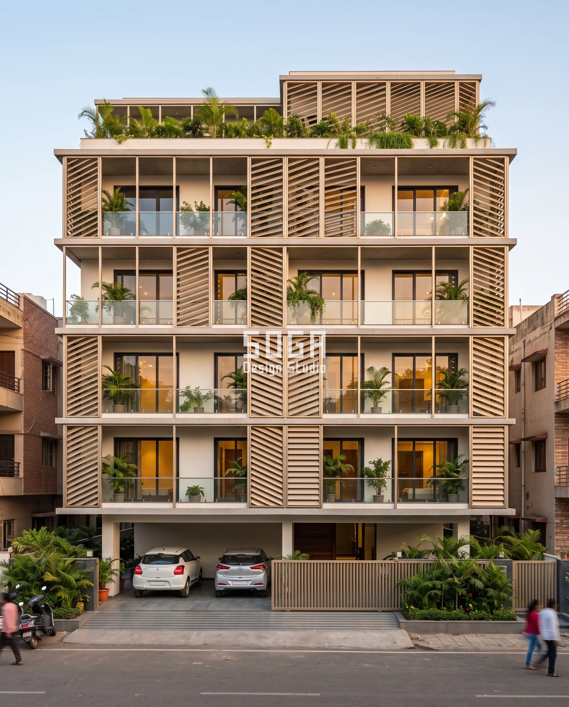
Blades of 50 × 150 mm at 120 mm centres measured normal to the blade face, which is the detail that decides everything else: hold the centres on that axis and the throat between blades stays 66 mm clear, so net free area sits at 55 percent whatever the blades are doing. The pitch then rakes from 10 to 50 degrees in five 10-degree steps, alternating direction cassette to cassette so the field reads as a chevron. A louvre is opaque to any sight line shallower than its own pitch angle, and a pedestrian 12 m off this Vijay Nagar G+3 reads the condenser bays at between 26.6 and 43.8 degrees of elevation – every one of them under 50. The extra turning at the steep end costs the fan under 4 Pa, which is nothing against the static head it already carries.
| Specification | Parametric Chevron Louvre |
|---|---|
| Product | 1,200 × 2,400 mm louvre cassette, 50 × 150 mm extruded blades at 120 mm centres, warm champagne polyester powder coat |
| Module | 1,200 × 2,400 mm cassette on a welded steel subframe, 50 × 150 mm blades at 120 mm centres normal to the blade face, 66 mm clear throat, 400 mm standoff |
| What varies | Blade pitch angle, 10 to 50° in five 10° steps |
| Head-on free area | 55% constant, net through the blade throat, at every pitch |
| Indicative rate | ₹2,700-3,450 per sq ft installed |
Parametric Ribbon Weave
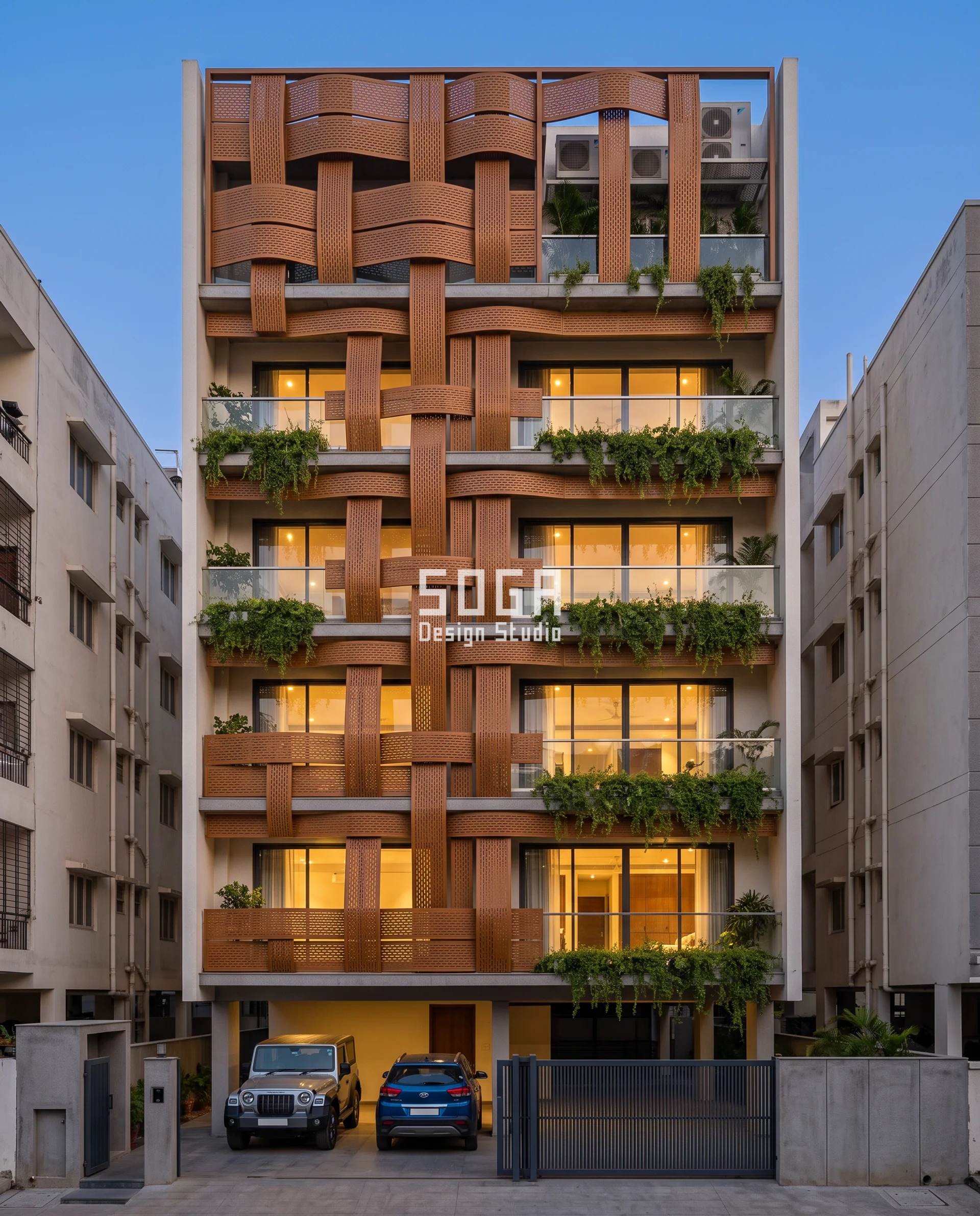
The densest of the five, and the only one that has to buy its free area back. Ribbons 400 mm wide interlace on a 640 mm pitch, so the weave on its own would leave 37.5 percent open; punching the ribbon at 31 percent – 30 mm holes on 51 mm staggered centres – brings the field to 57 percent, and 57 percent is the figure the eighteen outdoor units on this Kondapur G+5 are sized against. Crossing depth is the variable, 120 mm to 300 mm in six 30 mm steps, and at 300 mm the bay goes sight-proof beyond 38.7 degrees while the shallow bays still read 27 percent open at a 30-degree oblique. What a passer-by sees through a 30 mm hole at 12 m is the dark of the 400 mm cavity, not the machine standing in it.
| Specification | Parametric Ribbon Weave |
|---|---|
| Product | 400 mm wide folded-metal ribbon, warm timber-look sublimated finish, crossings expressed on a concealed steel carrier |
| Module | 400 mm wide folded-metal ribbon on a constant 640 mm weave pitch, 240 mm clear between ribbons, ribbon punched 31% open, crossing depth 120-300 mm, 400 mm standoff |
| What varies | Crossing depth, 120 to 300 mm in six discrete 30 mm steps |
| Head-on free area | 57% constant, head-on, at every crossing depth |
| Indicative rate | ₹3,050-3,700 per sq ft installed |
AC Outdoor Unit Placement In Elevation Design: Clearances, Brackets And The 400 mm Standoff
An outdoor unit needs clear discharge, not clear surroundings, and that single distinction is what lets a screen sit far closer than the blanket 600 mm rule most people quote. Daikin’s R32 split installation manual limits any wall in the path of the discharge airflow to 1,200 mm in height; VRV outdoor units ask for 1,000 mm at the front and 500 mm at the sides and rear. Our standoff is 400 mm face to face, constant across all five systems and every bay of each of them, and it does not breach those figures: each unit hangs in a 350 mm deep pocket recessed into the wall band so its discharge grille lands on the plaster line, and the 400 mm is measured clear from that grille to the back of the members. At 400 mm the plume has room to turn and leave through the 62 percent open lattice. At 150 mm it hits the backs of the members, stalls, and rolls back into the rear coil – that is recirculation, and it is how a screen that measures fine on paper still derates the unit. The 400 mm is also the working gap. A coil wash needs about 600 mm of clear reach at the rear face, so one panel per condenser bay is demountable on four captive M10 bolts – a 1,680 × 1,540 mm lattice panel on the Nashik system, one full cassette on the Pune shingle and the Indore louvre, three fins on a common carrier on the Surat rake, one ribbon bay in Hyderabad; below 300 mm nobody cleans it and it becomes a bird nest. The load case is just as unforgiving. A 1.5 TR outdoor unit is 38-48 kg dry and the bracket base is rated at 1.5 × dry weight, so 72 kg per unit, because the governing case is a technician putting his weight on the bracket during a gas charge. Anchors go into the RCC slab band or the RCC column only. Into AAC or infill blockwork the pull-out capacity is roughly a fifth of that in M25 RCC, and that is the commonest condenser failure on an Indian elevation: the unit does not fall on day one, it works loose across three dust seasons of vibration and then falls.
| Design parameter | Specification |
|---|---|
| Discharge face (fan side) | Any wall in the path of the discharge airflow, 1,200 mm maximum height; 1,000 mm clear for VRV outdoor units. Source: Daikin R32 split and VRV installation manuals |
| Intake face (rear coil) | 500 mm minimum to any solid surface. Source: Daikin VRV installation manual |
| Sides | 500 mm; 300 mm acceptable where only one side is obstructed. Source: manufacturer |
| Above | Clear to sky, or 1,000 mm minimum where units stack vertically. Source: manufacturer, plus anti-recirculation |
| Screen standoff (all five systems) | 400 mm face to face, cavity open at every floor. Source: SOGA – keeps the discharge plume out of the intake and stops the cavity acting as a flue |
| Service access (all five systems) | One demountable panel per unit, 600 mm minimum clear working opening – 1,680 × 1,540 mm on the lattice, one cassette on the shingle and the louvre, three fins on the rake, one bay on the weave. Source: SOGA |
| Head-on free area, the figure that never moves | 62% Parametric Depth Lattice · 58% Parametric Tilt Shingle · 60% Parametric Fin Rake · 55% Parametric Chevron Louvre (net, through the blade throat) · 57% Parametric Ribbon Weave – constant in every bay of each system |
| The one quantity each system varies | Member depth 110-260 mm · cassette tilt 0-25° · fin projection 90-240 mm · blade pitch 10-50° · crossing depth 120-300 mm – six or five discrete steps, never a continuous sweep |
| Cell opening and pitch (Parametric Depth Lattice) | 220 × 220 mm clear cell on a 280 mm pitch, 60 mm member face (220 + 60 = 280) – fixed on every floor and in every bay |
| Screen module (Parametric Depth Lattice) | 1,680 × 3,080 mm welded lattice panel – 6 cells wide by 11 cells high, so a panel edge always lands on a member, never mid-cell |
| Member section and finish (Parametric Depth Lattice) | 60 mm face folded-metal U-channel, champagne-gold anodised Class AA / Class II, 25 micron |
| Carrier frame (all five systems) | Hot-dip galvanised MS 60 × 60 × 6 SHS on serrated brackets with ±20 mm three-way adjustment, hung off 100 × 100 × 10 MS plates cast into each slab edge on M16 anchors, laterally tied every third floor |
| Unit bracket and isolation (all five systems) | 50 × 50 × 5 hot-dip galvanised MS angle, M12 chemical anchors into RCC only, base rated 72 kg, on 40 mm neoprene anti-vibration mounts |
The two details that decide whether it survives its first monsoon
- Water off the standoff cavity. The base of the 400 mm cavity is a 150 × 100 mm hot-dip galvanised MS channel falling 1:100 to a 50 mm slot outlet at each end of every bay, discharging over a 20 mm drip lip that stands 15 mm clear of the plaster. Without the fall, the cavity holds monsoon water and leaf litter and rusts the lateral ties out in two seasons. Without the drip lip, run-off tracks back along the soffit and stains the off-white plaster inside one monsoon. Condensate is separate and never shares that channel: a 25 mm uPVC line off each unit’s drain nipple, dropped on the wall side of the cavity where it cannot be seen through the lattice, sleeved through the slab band and manifolded into one 40 mm stack that discharges at plinth level into the plot soak pit – not onto the forecourt paving, and never onto the balcony below.
- Bracket, isolation and movement. Each unit sits on 50 × 50 × 5 hot-dip galvanised MS angle with M12 chemical anchors into RCC only, base rated at 72 kg, the unit on 40 mm neoprene anti-vibration mounts and a 25 mm nylon isolation washer at every bolt. That combination takes 80 to 90 percent of the transmitted vibration out of the slab, and it is the only part of the noise problem a facade can actually fix. On the screen itself, panel joints land on a member, a cassette edge or a ribbon crossing, never mid-opening, and the carrier frame gets a 15 mm movement joint every 6 m: a 6 m aluminium extrusion moves about 5.5 mm across the 40-degree surface swing between a January night and an April afternoon in Nashik, and it moves further again in Surat and Indore – a screen with nowhere to go bows visibly at mid-span, whichever of the five it is. Every metal-to-steel contact gets a 3 mm nylon separator washer against bimetallic corrosion.
Where This Method Stops Working – And What Never Works
This method costs facade depth, and there is a plot below which it is the wrong answer on all five systems. Add the varying quantity to the 400 mm standoff and the condenser bays project 527 to 700 mm from the structural face: 527 mm at the Pune tilt shingle, 550 mm at the Indore chevron louvre, 640 mm at the Surat fin rake, 660 mm at the Nashik lattice, and 700 mm at the Hyderabad ribbon weave, which is where this bites hardest. Most municipal bye-laws will read 700 mm as a projection into the setback rather than as a facade finish. On a narrow plot with a tight setback that projection simply is not available, and the weave is the first of the five to go. Below roughly 400 mm of usable projection, all five stop and you stop with them. The answer is not a shallower version of any of them, because a shallow lattice is a jaali – a light-and-privacy device sized for people at 35 to 50 percent openness – and at 12 m it hides nothing. Nor is the answer a tighter one, because that strangles the unit. The answer is to move the units off the street face entirely, into a rear service shaft or onto a terrace deck, and to say so to the client rather than sell them a screen that solves neither problem. The second limit is acoustic and it is unflattering. An open screen at 55 to 62 percent free area attenuates compressor noise by roughly 1 to 2 dB(A) on every one of the five, which is inside measurement error. None of these systems makes the building quieter. If noise is the complaint, the anti-vibration mounts are the fix and the screen is not. And for completeness, the three answers this question usually gets – a solid timber box, a tight-slat cover, and a hedge planted hard up against the unit. All three recirculate. All three cost tonnage. On the numbers above, doing nothing at all beats every one of them.
What Does A Condenser Facade Screen Cost In India (2026)?
₹2,300-3,700 per sq ft installed across the five systems, plus ₹9,500-16,000 per outdoor unit for the condenser-bay package, which is the same package on all five. The spread inside that band is fabrication, not depth alone: the Pune tilt shingle is a pressed cassette on a two-clip bracket and prices at ₹2,300-2,950, while the Hyderabad ribbon weave has an expressed crossing at every node and a punched ribbon on top of it, so it prices at ₹3,050-3,700. Indicative and itemised per project – Maharashtra, Gujarat, Madhya Pradesh and Telangana tier-2 rates, August 2026 – and they move with the metal market and with access. The depth premium is the line most people miss: a 260 mm member carries close to twice the folded metal of a 110 mm one, which is why only the condenser bays pay it and the other bays do not. The condenser-bay package is priced per unit rather than per square foot because it is the recessed pocket, the hot-dip galvanised bracket rated at 1.5 times dry weight, the anti-vibration mounts and the demountable panel – and it is the line a contractor will quietly delete if it is not itemised on its own.
| System / material | Indicative rate (per sq ft) |
|---|---|
| Screen skin, supply and fabricate – anodised or coated metal, any of the five systems | ₹1,350-2,450 per sq ft |
| Depth premium at the condenser bays only – the deepest step of whichever quantity varies | ₹380-640 per sq ft |
| Hot-dip galvanised MS carrier frame, cast-in plates, chemical anchors, lateral ties | ₹420-680 per sq ft |
| Base channel at 1:100 fall, slot outlets, drip lip, condensate line | ₹180-320 per sq ft |
| Erection, access and alignment | ₹260-430 per sq ft |
| Condenser-bay package per outdoor unit – recessed pocket, HDG bracket at 1.5×, anti-vibration mounts, demountable panel | ₹9,500-16,000 per unit |
| Parametric Tilt Shingle, Pune – installed | ₹2,300-2,950 per sq ft |
| Parametric Fin Rake, Surat – installed | ₹2,450-3,200 per sq ft |
| Parametric Chevron Louvre, Indore – installed | ₹2,700-3,450 per sq ft |
| Parametric Depth Lattice, Nashik – installed | ₹2,900-3,700 per sq ft |
| Parametric Ribbon Weave, Hyderabad – installed | ₹3,050-3,700 per sq ft |
| Installed range across all five systems, per sq ft of screen area | ₹2,300-3,700 per sq ft |
Every screen bay you build in front of a condenser also creates an upward-facing shelf that has to shed dust — the geometry that decides how often it needs washing is set out separately.
Related Reading
- parametric facade design in India
- our complete facade and elevation design FAQ guide for India
- G+3 and G+4 elevation design for Indian plots
- what facade maintenance and access actually costs
- stilt parking house facade design
Frequently Asked Questions
How much clearance does an AC outdoor unit need behind a facade screen?
Measure it per face, not as one blanket figure. Daikin’s R32 split manual caps any wall in the path of the discharge airflow at 1,200 mm high, and VRV units want 1,000 mm at the front and 500 mm at the sides and rear. We hold a 400 mm standoff from the discharge grille to the back of the screen members, with the cavity open at every floor.
Will a screen reduce my air conditioner’s cooling capacity?
Not at 55 to 62 percent free area with a 400 mm standoff – the added static resistance stays under 5 Pa on all five of the systems below, well inside the fan’s spare head. A boxed-in or tight-slat cover is a different story: it recirculates discharge back into the intake, and every 1 degree C of raised inlet air costs 2 to 3 percent of capacity, so 10 to 15 percent of the tonnage disappears.
How do you clean the condenser coil behind a fixed screen?
Make one panel per unit demountable. On the Nashik lattice that is a 1,680 x 1,540 mm panel on four captive M10 bolts, giving a 600 mm clear working opening at the rear coil; the other four systems hit the same 600 mm with one cassette, three fins or one ribbon bay. In Nashik the coils want washing twice a year – pre-monsoon Deccan dust and the post-Diwali particulate load – and a fixed screen turns that 20-minute job into a scaffold job.
Does an AC outdoor unit need to be covered from rain or direct sun?
No. Outdoor units are built to sit in the weather, and a solid hood over the top is the worst thing you can add, because it traps the discharge. Where units stack vertically, keep 1,000 mm minimum above each one and leave the 400 mm cavity open to the sky, so hot discharge leaves the face instead of feeding the unit above.
What does it cost to hide AC outdoor units on a house facade in India?
Budget 2,300 to 3,700 rupees per sq ft of screen area installed across the five systems – 2,300 to 2,950 for the Pune tilt shingle at the light end, 3,050 to 3,700 for the Hyderabad ribbon weave at the heavy end – plus 9,500 to 16,000 rupees per outdoor unit for the condenser bay, which covers the recessed pocket, the galvanised bracket rated at 1.5 times dry weight, anti-vibration mounts and the demountable panel. Tier-2 rates, August 2026, indicative and itemised per project.
Draw The Condenser Bay Before You Draw The Elevation
If your elevation carries eight to twelve outdoor units, the screen is not the first decision – the bay line is. SOGA works the condenser bays, the 400 mm standoff and the free area first, then picks which of the five systems suits the plot and sets its one variable against the actual street geometry, and only then draws the elevation. Send us the plan, the road width, the setback and the tonnage schedule, and we will come back with the system, the depth or angle per bay, the clearance check against the manufacturer’s manual, and a costed screen area. Write to [email protected].