A coin facade is bought as a drawing and delivered as a production run. Between those two states sit six operations on a shop floor, each with its own fixtures, operators and failure modes. Disc geometry, pattern parameters, load path and installation tolerance are settled before this begins — the territory of the complete coin facade guide. This article starts where that one stops.
Manufacturing is where a facade’s appearance is decided. What an elevation looks like at handover depends on whether the burr came off the rim before coating, whether the powder lot changed halfway through the second elevation, and whether the operator loading the racks knew which face the public sees.
The SOGA Coin Facade is a coin facade system developed by SOGA Design Studio for Indian fabrication, and the six-stage sequence below is the one the studio worked out with Indian fabricators while putting that system into production. It is written from that work rather than from a general account of shop practice.
Coin facade manufacturing runs in six stages: blanking circular discs from sheet, forming the disc rim or dish, deburring and edge treatment, applying and batch-controlling the finish, sub-assembling discs onto spines with spacers and fasteners, then inspecting, tagging and packing by installation zone so panels arrive on site in erection sequence.
From panel schedule to production plan
The design team hands over a schedule sorted the way a facade is sorted: by elevation, by bay, by grid position. The floor needs it sorted by diameter, dish depth, finish and cutting method instead. Converting one into the other is the first manufacturing operation, and it is paperwork, not metal. It matters because of tool changes: in facade order the schedule forces a die change every few parts; in batch order the press holds a setting for hours.
What must survive the re-sort is identity. Every disc in a graded field carries a position code that travels through all six stages. The most avoidable failure in the process starts here: the code goes on protective film, the film is stripped before pretreatment, and a rack reaches assembly as objects that look identical and are not. The fix is a mark etched on a concealed surface at blanking.
One disc of each type is then run through all six stages, signed off as a first article and retained rather than shipped. Lead time from released schedule to packed crates is set by the fabricator’s queue and the finishing line’s batch cycle, and it is quoted per project rather than as a standard figure. What can be dated is everything around it: see how a commercial facade lead time is back-cast gate by gate across India, Dubai, Singapore and Abu Dhabi.
Step 1 — Blanking the discs
Blanking produces the flat circular blank. Four methods are in common use, and the choice turns on what the edge looks like afterwards.
Cutting method selection and its effect on edge quality
Thermal cutting leaves a heat-affected zone and a recast layer, often with dross underneath. Both are harder than the parent material, both interfere with coating adhesion, and both must come off mechanically. Punching leaves a rolled-over radius, a burnished band and a fracture band with a burr — always on the same face, so the show face is nominated at drawing stage and the burr sent to the back.
| Method | Edge quality | Repeatability at high volume | Tooling cost | Suitability for varying diameters | Post-processing needed |
|---|---|---|---|---|---|
| Laser cutting | Clean profile; heat-affected zone, recast layer, dross | High; drift from optics, not tool wear | Low; none part-specific | Excellent — diameter is a parameter | Dross removal, edge dressing |
| Punching / press tool | Predictable roll-over, burnish and exit burr | Highest while sharp; degrades as it dulls | High per diameter; needs volume | Poor — one tool per diameter | Exit burr only |
| Waterjet | No heat-affected zone; slight taper; striated edge | Moderate; varies with speed and abrasive | Low; none part-specific | Excellent; takes thicker stock | Light dressing; striations show on directional finishes |
| Turret nesting | Nibbled profile; scallop marks on curves | High for repeat programmes | Moderate; standard tooling | Good within the library; odd sizes are slow | Scallop dressing on every disc |
The recurring blanking failure is not a cutting fault. It is sheet orientation. On a laser bed the underside picks up spatter from the slats, so an operator who flips a sheet mid-run leaves half a batch marked on the wrong side — invisible under mill finish, obvious after coating.
Nesting and offcut strategy
Circles nest badly, and the material between the blanks is waste that sits in the price. Nesting mixed diameters into one sheet recovers a share of it, and only works if the schedule releases several diameters together. Two constraints limit how far that can be pushed. Pack too tightly and the skeleton goes flimsy, parts tip up into the cutting head, and the head is damaged. Micro-tabs leave a witness on every disc, so they go on the rim edge that is later formed over. SOGA fixes tab positions in the cutting package rather than leaving them to the nesting station, because a tab placed for the nest’s convenience lands on the show face.
Step 2 — Forming the disc
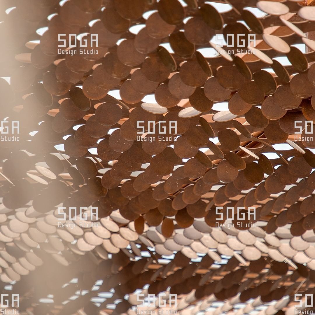
Forming turns a flat circle into an object. The pillar guide explains why that rim matters; this is how it is made.
Rim forming, dishing and springback
The blank is degreased, lubricated, then located in the die — against its outer diameter in a nest ring, or on a pilot feature. That choice matters: the nest ring transfers blanking ovality into the formed part, while a pilot decouples the two. A blank holder applies pressure to the flange, the punch descends, the dish is drawn and the rim turned. Press capacity is sized to the disc rather than to the facade, and it is confirmed against the specific disc before a run is scheduled.
Three failure modes live in that sequence. Rim wrinkling occurs when holder pressure is too low and flange material folds; it cannot be removed afterwards. Thinning and splitting is the opposite condition, showing as a bright band at the dish transition before it shows as a crack. Galling is progressive: lubricant breaks down, material transfers to the tool, and scores every part after it.
Springback is not a defect. It is elastic recovery, compensated by over-forming a calibrated amount that is established at first-article trials for that disc and that material batch, and recorded on the tool sheet. The compensation is not constant. It shifts with material batch, with sheet thickness within tolerance, and with tool temperature.
Forming quality checks per batch
Because springback drifts, first-article approval is not enough. Three checks run through every batch at a stated interval, written into the inspection plan rather than left to the operator:
- Dish depth, with a go/no-go profile gauge rather than a measurement, so the operator makes a pass or fail decision, not a judgement.
- Rim plane flatness, on a surface plate. A rim out of plane will not seat against its collar, carrying rotation error into assembly.
- Ovality, with a ring gauge. Ovality from blanking is amplified by forming, and an oval disc in a regular field is visible from the street.
Any fail stops the run rather than triggering a sort. That rule came out of SOGA’s fabrication trials: sorting a bad batch hides the drift that produced it, and the drift continues.
Step 3 — Edge treatment and deburring
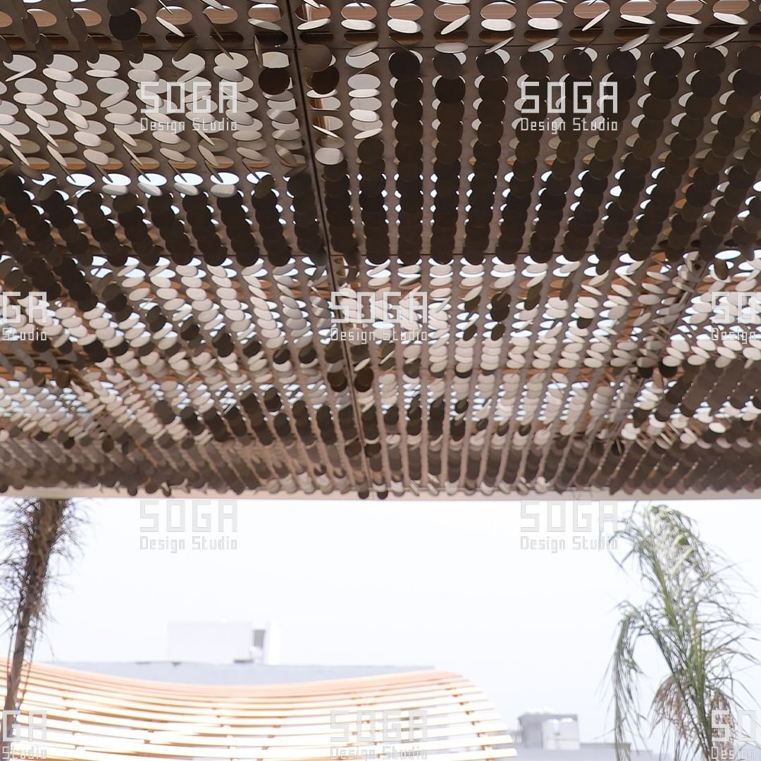
Deburring decides how a coin facade looks at ten years, and it is the first operation compressed when a programme slips. Burrs come from two mechanisms. Mechanical cutting drags rather than shears at the exit face, leaving a raised lip around the circumference. Thermal cutting leaves dross and a hardened recast layer, the more insidious because it is not visible.
Both matter for one reason. Coating flows away from a convex arris, so film is thinnest over a sharp edge, and over a burr it is a fraction of nominal. That is where corrosion starts, and on a disc field the rim is where the eye goes. Edge preparation is therefore specified as a radius, not as an instruction to remove burrs, and the radius is stated on the drawing with the method used to verify it.
Vibratory mass finishing works the whole part at once; drag finishing fixtures each part and gives better rim control. The named failure is media entrapment: a formed disc is a shallow tray with a turned rim, media lodges behind it, survives the rinse and works loose in the cure oven, leaving a hard particle bonded to a coated disc. Prevention is media sized against the rim geometry, an inspection station after the rinse, and air on the rim before finishing.
Step 4 — Finishing

Finishing is applied after forming, never before. The line runs degrease, etch, rinse, pretreatment, final rinse, dry-off, coat, cure. Rinse quality is monitored by conductivity, because contaminated rinse carries salts onto the part and they sit under the coating as future blisters. Dry-off matters more on a dished part than a flat one, because water pools in the dish and the rim return.
Racking belongs on the drawings. Every disc hangs from something and the hanging point leaves a mark, and a disc has no hidden edge — so the rack point goes to a concealed rear boss or a covered fixing hole. Racking by the rim marks the most visible feature of the panel.
Powder coating a dished part brings a specific effect. Electrostatic powder is repelled from recesses by the Faraday cage effect, so film builds thickly on the rim and thinly at the dish centre. Thickness is checked at both, against the dry film thickness range the coating system’s own specification requires. Cure is the other trap: unevenly loaded racks heat unevenly, and an under-cured disc passes visual inspection then fails adhesion.
Batch control, colour consistency and orientation of directional finishes
Finish consistency across thousands of discs is a logistics problem, not a chemistry one. Powder lots and anodising tank loads vary slightly, and neither variation can be eliminated. The response is to control where it lands.
Two rules do most of the work. First, retained reference samples: one approved sample kept from every batch, compared under fixed lighting and archived for future replacement discs. Second, batch mapping — lots distributed across the facade rather than allocated elevation by elevation. Give one elevation entirely to one lot and a tone shift appears as a hard line; spread the same lots across all elevations and it is imperceptible. SOGA plans both before finishing begins; neither can be applied to parts already coated.
Directional finishes add a problem circles create by themselves. A disc has no natural up, so grain can be indexed anywhere unless a datum is defined — a fixing hole, a keyway, a stamped mark, set at blanking and carried through finishing and assembly. Without it, grain points in every direction and the elevation reads as noise, which cannot be corrected after installation.
Step 5 — Sub-assembly: spines, spacers, fasteners

Sub-assembly moves work off the scaffold into a lit, seated, jigged environment. Every operation completed here is one not done at height in gloves.
Discs go onto their spine in a bench fixture with hard stops setting pitch, so pitch is a property of the fixture rather than of a measurement. Where the collar is keyed, the key sets rotation, and the keyway must be indexed to the same datum used for the finish grain. The pillar guide explains why a disc needs two restraint points rather than one; on the floor, the second restraint is that keyway. The bench fixture SOGA issues with the assembly drawings accepts only the intended disc type, the cheapest guard against transposition in a graded field.
Four things go wrong at the bench. Sequence error, where discs of different dish depth look near-identical in a crate and get transposed. Thread galling, a lubrication and speed issue, which seizes a fastener halfway in and leaves a joint neither tight nor removable. Missing isolation washers at dissimilar-metal interfaces, invisible for two years and then visible as staining below every fixing. Over-tightening, which leaves a dimple in the dish. Assemblies are weighed against the site’s handling limits, which are agreed with the installer before packing logic is fixed rather than discovered at the gate.
Step 6 — Inspection, tagging and packing
Final inspection is defined by viewing condition, not by scrutiny. A disc examined at arm’s length under a bench lamp fails for marks nobody sees from a footpath, so the specification states a viewing distance, a lighting condition and an angle. Checked here: finish and film thickness by sample, dish depth, pitch across the spine, rotation against the datum, and fastener locking. Failures go to a quarantined rack, not back into the flow.
Every assembly then carries a durable tag with position code, batch identifier and an orientation arrow. An assembly symmetric in silhouette is rarely symmetric in grain or dish direction, and an installer at height will not stop to work that out.
Packing is planned by installation zone and erection sequence, where manufacturing meets coin facade installation sequencing. Crates are built so the first assembly needed is the first one reachable, with labels readable when stacked, and rims get dedicated edge protection. Spares are packed from their zone’s own batch, so a replacement five years later matches the discs beside it rather than the project average.
Common coin facade manufacturing defects and how they are caught
| Defect | Where it originates | How it is detected | How it is prevented |
|---|---|---|---|
| Rim wrinkling | Forming; holder pressure too low for the draw | Visual against the retained first article | Holder pressure set at first article and logged |
| Media entrapment | Deburring; media lodging in the rim return | Post-rinse inspection and air blow-off | Media sized against the rim geometry |
| Polished flat on the rim | Deburring; over-running in the vibratory bowl | Comparison to retained sample under raking light | Cycle time fixed and timed, not judged |
| Thin film at the dish centre | Finishing; Faraday cage effect at the recess | Thickness measured at the centre, not the rim | Gun settings trialled at first article |
| Tone banding | Finishing; one lot allocated to one elevation | Comparison to retained samples before packing | Batch mapping planned before finishing |
| Random grain rotation | No datum on a rotationally symmetric part | Visible under raking light once assembled | Physical datum set at blanking |
| Transposed disc types | Sub-assembly; similar dish depths in a graded field | Position code check at final inspection | Fixtures taking only the intended part |
| Rim damage in transit | Packing; unprotected rims and heavy stacking | On unpacking, when it is a site problem | Rim protection and a stated stacking limit |
What a fabricator needs from the design team before starting
A production floor starts on a package, not on design intent, and a missing item becomes an operator’s decision.
- A disc type schedule with counts — diameters, dish depths and rotation settings listed separately, each with a quantity and a position code.
- Flat pattern development for every disc type, with forming allowances stated rather than derived on the floor.
- A nominated show face and a datum feature, both marked at blanking, fixing burr direction, grain orientation and keyway indexing.
- Edge preparation stated as a radius, with the condition required before finishing.
- A finish specification describing a process — pretreatment, coating system, film thickness at the dish centre, cure schedule and adhesion testing.
- Sub-assembly drawings with torque figures, locking method and isolation components, plus a coding convention that survives finishing and packing zones matched to the install sequence.
A package answering all six can be quoted accurately and run without interpretation. One that does not will be interpreted on the floor, and those interpretations are not recorded.
How SOGA developed this production sequence
Every operation in this sequence already existed on Indian shop floors: blanking, drawing, deburring, coating and bench assembly are ordinary work, run daily and run competently. What did not exist was a sequence that held one disc identical to the next across a run of thousands. Individually the parts passed; as a field they did not, because each operation was controlled to its own standard rather than the one the elevation needed.
SOGA developed the sequence by running it. Prototypes established what could be formed consistently in thin stock. Fabrication experiments moved the work onto a production floor at real batch sizes, where most of the assumptions failed. Structural studies and installation testing on a mock-up settled the sub-assembly; manufacturing optimisation followed once the disc family was closed.
Two things changed between the first production run and the settled sequence. The first was fixturing. The first run located blanks in the die against their outer diameter, which carried blanking ovality into the formed part; the sequence now locates on a pilot feature, so a blank slightly out of round is still formed round. Bench assembly moved the same way, from measured pitch to hard stops, making pitch a property of the fixture rather than of an operator’s tape.
The second was first-article discipline. It began as a gate passed once at the start of a run; it is now a retained physical part held at the bench, checked against on go/no-go gauges through the run, because springback drifts and a run approved at the first part is not a run approved at the last.
Development sat inside the six-months-to-a-year range these systems take.
It is manufacturable in India because it needs no machine an Indian metal shop does not already have — only the operations it runs daily, sequenced, fixtured and inspected against one reference.
SOGA Design Studio is a parametric and computational architecture practice based in Gurugram, working across India, Dubai and Singapore, specialising in facade systems engineered for local fabrication.
Frequently asked questions
Why does edge quality matter so much on coin facades?
Every disc edge is visible and catches light, so burrs and inconsistent edges read across the whole facade rather than disappearing into a joint. Coating is also thinnest over a sharp edge, which makes the rim the first place corrosion appears, so edge treatment is a visual requirement rather than only a safety one.
How is finish consistency maintained across thousands of discs?
Finishing is batch-controlled with retained reference samples compared under fixed lighting, and batches are mapped to facade zones so variation is distributed rather than concentrated. Allocating one lot to a single elevation produces a visible tone line.
What causes springback in formed discs?
Elastic recovery after forming, which is normal rather than a fault. It is compensated by over-forming a calibrated amount established during first-article trials, and monitored through the run because it shifts with tool temperature and material batch.
Are discs assembled in the factory or on site?
Sub-assembly into spines or cassettes is usually done in the factory, on a bench fixture with hard stops, to protect quality and reduce work at height. Torque control, isolation washers and rotation indexing are all more reliable seated at a bench.
What the production floor actually controls
The pattern is designed once and manufactured thousands of times, and each of those times is a chance for it to be made slightly differently. A coin facade that looks right at handover is one where the burr came off before the coating went on, the lots were mapped across elevations instead of down them, and the crates opened in the order the installers needed.
None of it is visible in a photograph, which is why it is rarely written about — and it is the reason parametric facades became buildable here at all, the subject of how parametric facades became manufacturable in India.
This sequence was worked out on Indian shop floors, with Indian fabricators, against Indian stock and Indian programmes. It runs elsewhere without amendment, for an ordinary reason: a floor disciplined enough to hold a disc field together here needs nothing added to hold one anywhere else.
Our manufacturing sequence and inspection checklist for coin panels can be reviewed alongside your fabricator’s capability.