Computational design in India is written about in two registers. One is theoretical: complexity, emergence, form-finding, a vocabulary borrowed from research that rarely touches a project programme. The other is instructional: which button produces which surface. Between them sits the part practitioners actually spend their weeks on, and almost nobody writes it down — the conversion of a parametric model into information a fabrication shop can act on without telephoning the designer.
The conversion is not an export. A model is a set of relationships: this panel centre derives from that grid, the grid from a structural bay, the bay from a survey datum. A fabrication drawing set is the opposite kind of document — a description of physical objects, each with a fixed size, a stated tolerance, a finish, an identity and a place in a sequence. Getting from one to the other means deciding what the design will fix, what deviation it will accept, and which numbers in the model are load-bearing for manufacture. Treating that as administration is why parametric facades arrive on site as problems.
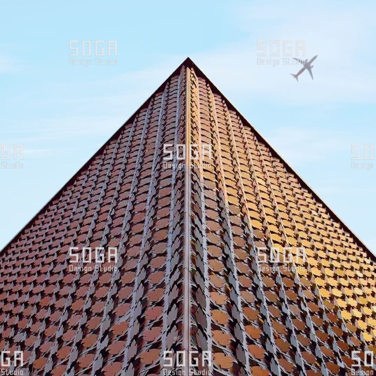
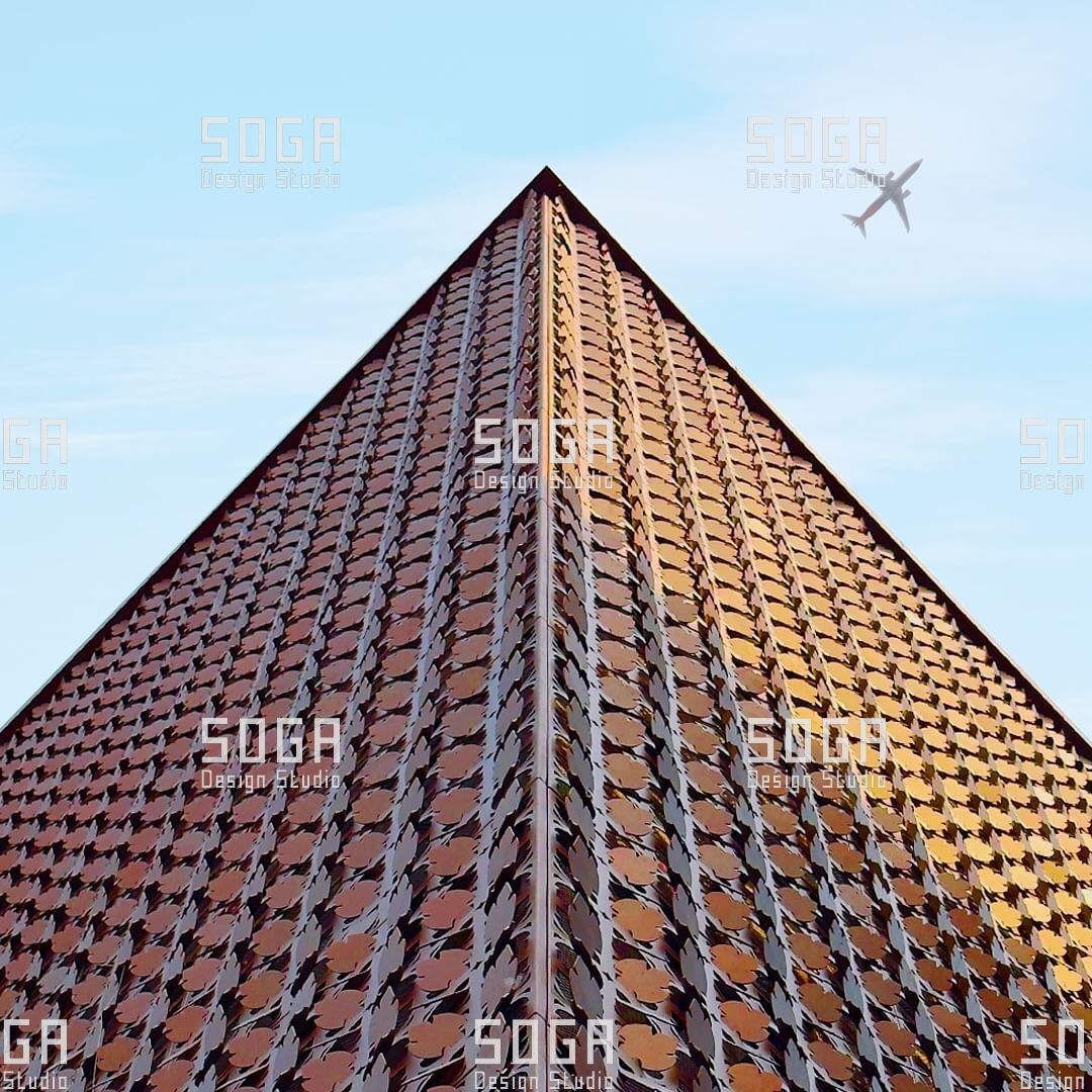
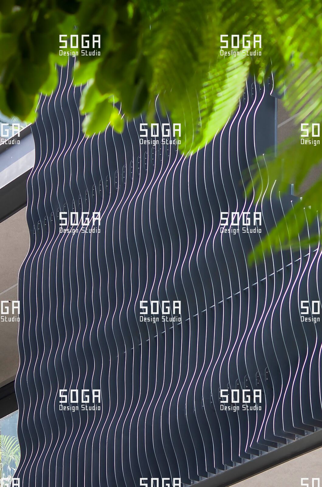
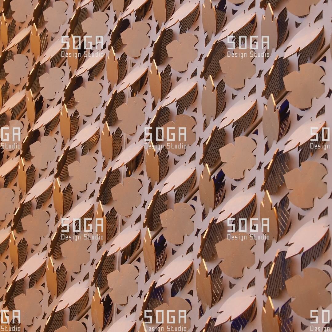
This article sets out the workflow in five stages, in the order a project runs them, and names where each breaks. It is the workflow SOGA Design Studio developed for Indian projects and runs on live work — the method behind the SOGA Coin Facade, SOGA Sequin Facade, SOGA Slicing Fin Facade and SOGA 3D Block Facade rather than the systems themselves. What follows is a practitioner’s account of a documentation process rather than a survey of the field, and the failure modes named in it are ones the studio had to engineer its way out of before the systems could be offered on a project.
Computational facade design uses rule-based parametric modelling to generate facade geometry, then converts that geometry into fabrication-ready data. The workflow moves through design rules, rationalisation into repeatable panel families, extraction of per-panel data such as size, angle and fixing position, and finally shop drawings with the tolerances a fabricator needs.
What computational facade design actually produces
The output of a computational facade process is not a surface. It is five deliverables, and a project is in trouble whenever it has some and not the others.
A rule set: the logic that generates the facade, re-runnable when an input changes. A rationalised panel family: a countable set of part types, with the number of unique parts stated. A panel database: one record per panel, holding every value a machine or an operator needs. A fabrication drawing set: the instructions the shop floor builds from. And a verification record: first-article measurements, mock-up findings, and the changes each forced back into the other four.
Underneath all five sits one distinction. Design intent describes what the facade should be: the pattern, the gradient, the depth range. Fabrication information describes what one part is: this blank, these fold lines, this hole at this distance from this edge, this finish, this identity code. Design intent tolerates ambiguity, which is what makes it useful early; fabrication information tolerates none. Projects fail here when a design-intent document is issued into a fabrication process and the shop floor resolves the ambiguity itself, quietly and inconsistently, several hundred times.
The model and the drawing set are not competing versions of one thing. They hold different information and carry different authority.
| Item | The parametric model | The fabrication drawing set |
|---|---|---|
| Generating rules and dependencies | Authoritative; the only place they exist | Not shown; only their results appear |
| Panel positions and dimensions | Generated, and re-generated when inputs change | Fixed values, dimensioned from stated datums |
| Tolerance | Not naturally held; authored deliberately as an attribute | Stated against every dimension that matters |
| Fixing adjustment range | Present only if modelled as a range | Drawn, with permitted movement written per axis |
| Finish and process | A code or attribute at best | Full process description, preparation to cure |
| Forming allowances | An assumption behind every flat blank | Stated, so the shop can check it against its tooling |
| Revision status | A file version, understood by whoever opened it last | A revision on every sheet, change identified |
| Contractual standing | None | What gets built, and what gets argued about |
The drawing set is the deliverable. The model is the only place the design can be changed safely. Both are true at once, and holding both is the skill.
Stage 1 — Design intent as rules, not shapes
A shape is a result. A rule is the relationship that produced it. The difference matters because facade projects change late.
When a floor level moves, a grid shifts or a client adds an opening, a modelled shape has to be redrawn and every downstream number rechecked by hand. A rule regenerates: the field re-solves, the schedules recount, and the work reduces to verifying that the regeneration behaved. On a facade of a few thousand panels, that is the difference between absorbing a change and repricing the package.
Writing intent as rules means being explicit about dependency, each link stated once and in one place. The recurring failure is a definition that looks parametric but is anchored to frozen input: geometry drawn by hand at the start, then referenced by every rule after it. The model regenerates happily and produces the same wrong answer faster.
Two disciplines make a rule set survive its author: internal documentation — named groups, stated units, a note wherever an assumption was made — and version control that records what changed. A definition only one person can open safely is a project risk, and facade programmes run long enough that people move on.
Parameters worth exposing, and parameters worth locking
Every exposed parameter promises that changing it re-solves everything downstream correctly. Expose one that does not keep the promise and you have built a mechanism for silent error.
Worth exposing are the values the design conversation will genuinely revisit. Pattern pitch. Density gradient and its direction. Rotation or depth range. Opening positions. Zone boundaries. These are what a client or a consultant will ask to move, and the model earns its cost by answering in an afternoon.
Worth locking are the values with engineering behind them. Material thickness. Inside forming radius. Edge return. Fixing offsets. Designed adjustment range at the bracket. Minimum joint width. Each was settled by a calculation, a trial or a test, and changing it invalidates that work with no visible signal in the model. Locked values belong in one controlled table with a named owner. SOGA holds that table outside the definition, so a value settled by a test cannot be changed by opening the model.
The failure mode is common. Late in a project someone adjusts an exposed parameter for a visual reason. The geometry updates. The schedule updates. The drawings, already issued, do not, and the shop is soon cutting to one version while the site sets out to another. Parameter changes after the database is issued are formal revisions, not modelling.
Stage 2 — Rationalisation

Facade rationalisation replaces continuously varying geometry with a discrete set of manufacturable parts, while keeping deviation from the ideal surface inside a stated band. Three words there carry weight.
Discrete, because manufacturing is economical only when a setup runs more than once, and a continuously varying model contains no repeats at all — every panel differing by a fraction the eye cannot see and the shop floor pays for in full. Manufacturable, because the target is fewer setups, not fewer parts in the abstract. Stated, because rationalisation without a written deviation limit cannot be checked.
Rationalisation is not simplification. Simplification removes information from the design; rationalisation keeps what the design does and changes how it is built — stepping a continuous parameter into increments, snapping dimensions to a module, substituting single-curvature geometry for double curvature, and letting the joint absorb the residual. That last move does most of the work, because the joint is the tolerance sink of a panelised facade. A deliberate shadow gap carries far more rationalisation headroom than a flush plane.
Reducing unique parts without flattening the design
The method is to find which parameters the eye reads, then spend the part budget only on those.
At the distance facades are seen from, viewers read alignment, rhythm, gradient direction and the way light falls. They do not read a small difference in panel width, or a depth step that shifts slightly between neighbours. Variation carried by position, rotation and depth stepping therefore survives rationalisation almost intact; variation carried by panel outline is expensive and largely invisible.
Rationalisation is tested by comparison, not assertion. The rationalised set is checked against the ideal surface at real viewing distances and real sun angles. Deviation that disappears at distance is free. Deviation that appears along a sightline running the length of an elevation is not, however small the number attached to it. SOGA runs that comparison at the real viewing distance and under raking light before a family is agreed, because a deviation that disappears on a screen is not the deviation the street is shown.
The failure mode is rationalising uniformly. One step size across a whole facade spends the part budget evenly, when the elevation is not viewed evenly. Eye-level areas need finer resolution; high zones, oblique zones and rear elevations tolerate coarser steps. The count is measured before and after, and the reduction from ideal geometry to a rationalised family is usually large enough to change how the facade is priced rather than merely tidy the drawing set.
Panel families, tolerance bands and repeat logic
A panel family is a group of parts sharing a forming setup and differing only by scheduled dimensions. Members are made in one run with one tool arrangement; a new family means a new setup, a new first-article inspection and a new chance for a batch to go wrong. Counting families matters more than counting parts, and the two are often quoted interchangeably.
The tolerance band is the permitted deviation of a rationalised panel from the ideal surface it stands in for. It has to be a number, reconciled against joint width and fixing adjustment, and recorded beside the rationalisation decision. Without it nobody downstream can judge whether a proposed substitution is legal, and substitutions are proposed constantly. The band is set for the project and agreed before rationalisation starts, not discovered afterwards.
Repeat logic describes how repeats are distributed. Contiguous repeats — long runs of one part in one zone — are the cheapest thing a facade can contain, because the machine runs and the crate fills in installation order. The same parts scattered across four elevations give an identical part count and a much harder logistics problem. Grading a pattern zone by zone rather than continuously converts scattered repeats into contiguous ones without changing what the facade looks like.
Stage 3 — Panel data and the fabrication database
This is the stage where geometry becomes rows. Every panel turns into a record, and that record — not the model, not the drawing — is what the rest of the project runs on.
The panel database is the single source of truth for counts, cutting files, finishing batches, packing lists, the installation sequence and the drawing set. Drawings become views of it rather than independent documents, so a change made once propagates everywhere. When that breaks — a drawing edited by hand, the record left alone — the project carries two versions of reality, and the divergence is discovered on a scaffold.
Numbering is the load-bearing part. An identifier must be generated by the model, printed on the drawing, marked on the part in a way that survives finishing and handling, and referenced in the packing list and installation programme. It should encode location rather than order of creation: elevation, zone, grid line, course. An installer holding a part then knows where it goes without a lookup table. The convention SOGA issues encodes elevation, zone, grid line and course in that order, so a crate can be sorted on the ground without opening the database.
Two rules protect the numbering. Identifiers are never reused; a deleted panel’s identifier is retired rather than reassigned. And they are never regenerated wholesale after a design change, because renumbering invalidates every document, cut file and crate label already issued. Where a change is unavoidable, affected records take a revision suffix. Renumbering halfway through fabrication is one of the few mistakes here that cannot be recovered cheaply.
Minimum data fields per panel
A record missing any of these leaves a decision to someone downstream, who will make it without reference to the design.
- Panel identifier — unique, location-encoding, never reused.
- Elevation, zone and grid reference — where the part belongs.
- Family or type code — which forming setup produces it.
- Flat blank reference — the developed outline the cutting operation uses.
- Form data — fold line positions, angles, and the inside radius assumed.
- Face orientation and handedness — the visible face, and whether a mirrored twin exists.
- Edge and return condition — exposed edges identified, since they govern deburring effort.
- Fixing positions and type — dimensioned from the panel’s own datum.
- Finish code and batch reference — for matching replacements years later.
- Mass — for lifting, bracket loading and handling method.
- Nesting or sheet reference — for traceability back to stock.
- Revision — with the superseded version identified.
- Crate and sequence number — packing follows installation order.
Two of those fields are habitually omitted and both cost money. Handedness, because mirrored panels look identical in a model and are useless made the wrong way round. And marking, because parts of different depth are indistinguishable in a crate, and a graded facade installed from unmarked stock produces a gradient that is subtly and permanently wrong.
Stage 4 — Fabrication drawings the shop floor can use
A fabrication drawing exists to remove judgement from the shop floor. Everything on it is dimensioned from a datum an operator can physically find, carries a tolerance, and refers to one part. Nothing is scaled, inferred or approved later.
The change in reference system is what people underestimate. Design drawings dimension from building gridlines, which is right for their purpose and useless at a press: a fabricator holds a blank, not a building. Every dimension on a fabrication drawing runs from a feature of the part itself — a formed edge, a datum hole, a marked corner. Chained dimensions accumulate error, so critical features are dimensioned from one origin rather than from each other.
| Attribute | Design drawing | Fabrication drawing |
|---|---|---|
| Purpose | Communicates intent, proportion and relationship | Instructs production of one specific part |
| Dimension basis | Building gridlines and levels | Datums on the part itself, locatable on the floor |
| Tolerance shown | Rarely; assumed to follow a general note | Against every dimension governing fit or appearance |
| Material callout | Generic panel material and finish | Grade, thickness, condition, finish process, film requirement |
| Fixing detail | Indicative, showing principle | Located and dimensioned, with fastener and locking method |
| Panel ID system | Absent or by type only | Unique per panel, matched to database and crate |
| Who reads it | Architects, consultants, approving authorities | Cutting and press operators, finisher, inspector, installer |
| Consequence of error | Rework in the drawing office | A batch made wrong, material already consumed |
What a fabricator needs that a design drawing never shows
The list is short and usually missing from the first issue.
Flat blank development with the forming assumptions written on it. A blank is correct only against a stated inside radius and bend allowance. Issue one without them and the shop applies its own, which may be right and may be off by enough to move every hole.
Forming sequence. Which fold happens first, and where the operator holds the part. On panels with returns on more than two edges, one fold order works and several trap the tool.
Visible face, finish direction and edge exposure. Which side the building sees, which way a directional finish runs, which edges are read from close range. These decide deburring effort and whether a coating is acceptable at the arris.
Inspection points. Which two or three dimensions are measured on every part, and which are checked on first article only. A shop asked to measure everything measures nothing carefully.
Marking method and location. Where the identifier goes and by what process, positioned to survive forming and finishing and stay readable during installation.
Packing and handling. How parts stack, what separates them, which face goes up.
Equally important is what the drawing must not contain. No renders. No mood imagery. And no note reading “to architect’s approval” against a dimension, because a drawing that defers a decision to the moment of manufacture has not made it.
Stage 5 — Verification: mock-ups, first-article inspection, feedback loop
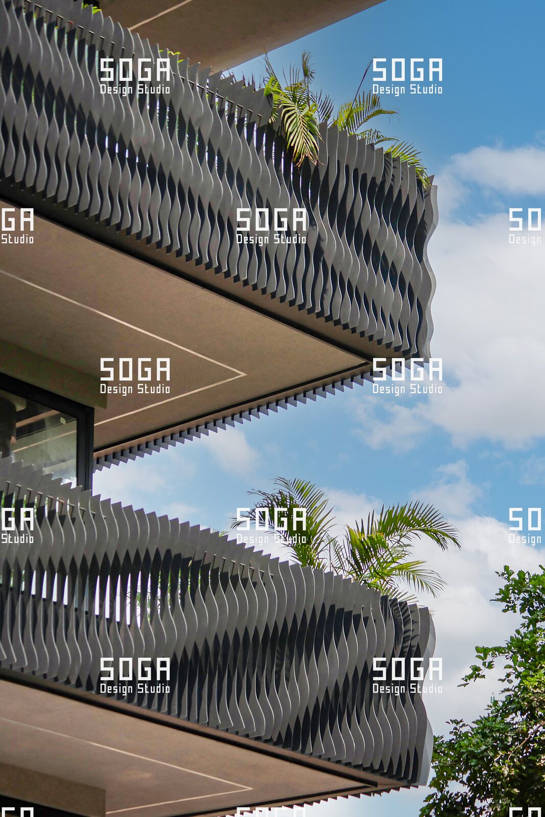
Verification tests two things at once: the parts, and the documents behind them.
First-article inspection takes the first part out of a new family and measures it against its drawing before the run continues. It catches three repeating errors: springback drift, where formed geometry relaxes off the tool by more than the allowance assumed; datum misinterpretation, where the operator measured from a different edge than intended; and transposed dimensions, where two similar values have swapped in a schedule. All three are cheap at the first part and expensive at the four hundredth.
The mock-up verifies the assembly, and it is the last honest test of the drawing set. The measure is not whether it looks right. It is how many times the installers had to ask a question. Every question is a defect in the documentation, and each will be repeated across the elevation by people with less supervision and less time. Log them, and answer each with a drawing change rather than a conversation. SOGA treats that log as the mock-up’s principal output: the assembly is expected to work, and what is under test is whether the documents did.
The feedback loop is where most workflows quietly fail. A problem found at verification gets fixed on the shop floor — a hole moved, a fold angle adjusted, a bracket packed out — and the fix works. If it does not travel back into the model and the database, the next batch reverts, because the original geometry is what the cutting files still say. The undocumented shop fix is the commonest cause of a facade that fits in its first bay and not its fortieth. No change is real until it exists in the model, the database and a reissued drawing.
Where computational workflows fail on Indian projects
The failures are rarely technical. They are organisational, they repeat, and each is preventable.
Drawings traced by hand from the model. The design then changes and only some views are retraced. This is the origin of most drift, and the reason drawing production should be driven from the database.
A 3D file issued instead of a drawing set. A fabricator handed geometry with no dimensions, tolerances or inspection references is being asked to author the fabrication information without the engineering behind it. Where a shop can do that, it should be a stated scope with a fee. Where it cannot, it will interpret, and operators interpret differently. Cut files without drawings are the same failure one step on: parts get made and nothing exists to inspect them against.
No owner for the panel database. When responsibility for the records is diffuse, everyone edits and nobody reconciles. One named person should hold the database and issue from it.
Fabrication sub-let mid-project. A drawing set tuned to one shop’s tooling arrives at another with different press capacity and tolerances. It has to be re-checked against the new capability.
File degradation between parties. Curves converted to polylines in translation, units misread, layers flattened, precision truncated. Each produces geometry that looks correct and measures wrong. Translation steps should be minimised and every received file checked against a known dimension before use.
Approval treated as a visual exercise. Fabrication drawings reviewed as images, approved for appearance, returned with the dimensions unread. An approval that does not check datums, tolerances and identifiers is not one.
Coordination with structure, MEP and site survey
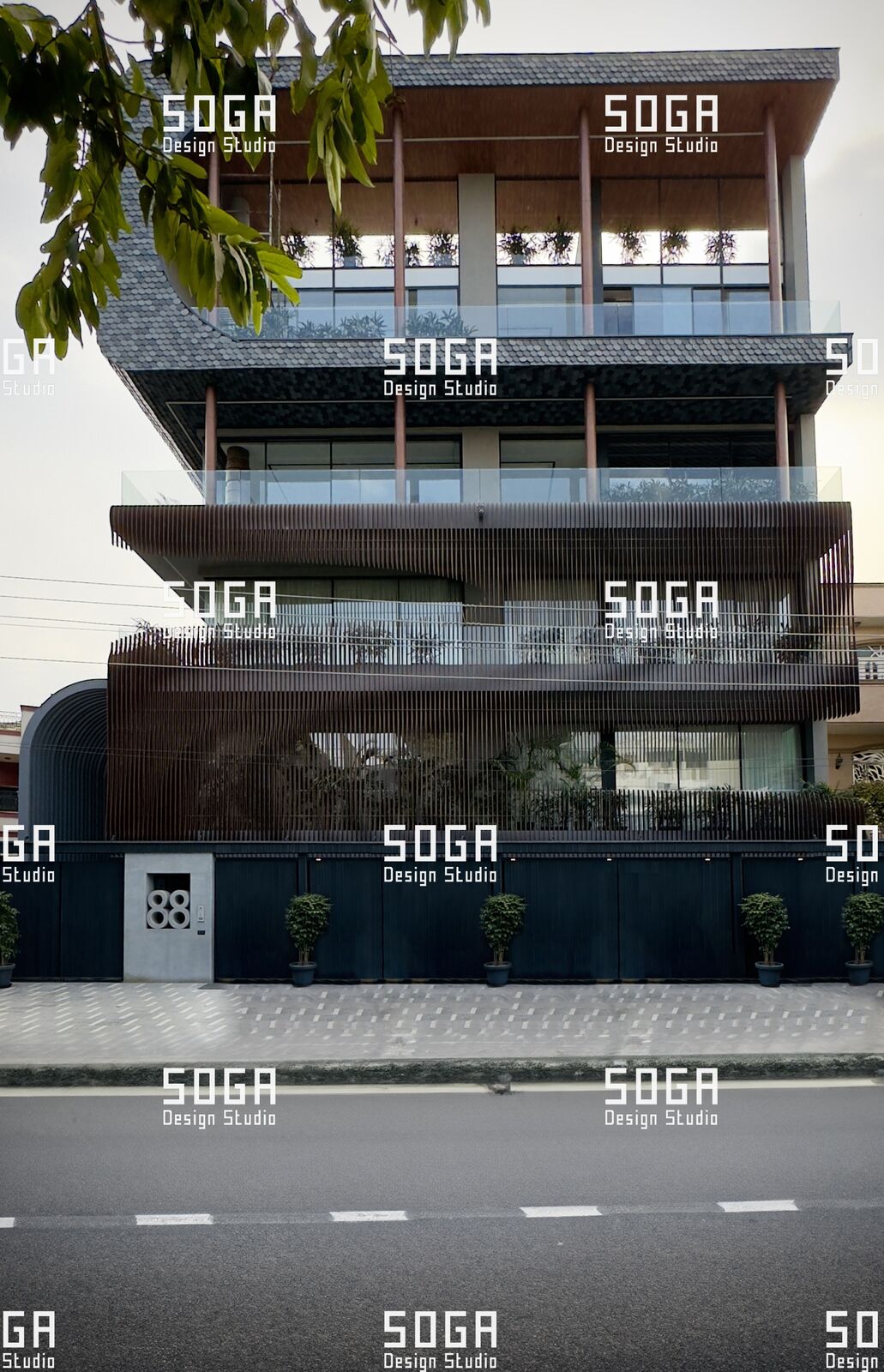
A facade model is a proposition about a building that does not exist yet. Coordination replaces the proposition with measurements.
The first substitution is the as-built survey. Frames deviate; that is normal and covered by construction standards. What is not acceptable is generating final panel data against the theoretical frame and finding the difference at installation. The survey produces a point set, the point set a deviation map, and the map is compared against the adjustment designed into the brackets. Where demand exceeds range, the resolution is a documented change decided in the drawing office rather than improvised at height.
The second is anchor coordination. Cast-in fixings are set out early, exactly when the facade model is least settled. Reinforcement congestion, slab edge condition, movement joints and post-tensioned zones all constrain where a bracket can land. Freeze anchor positions and zones of permitted adjustment first, then let the panel data solve within them.
The third is everything behind the skin: drainage outlets, lighting and cable routes, maintenance access, louvre openings, signage backing, and the void depth each needs. Late collisions appear here, because services are coordinated against the structural model while the facade occupies a zone outside it. The facade belongs in that model as an occupied volume, not a surface.
The fourth is the interfaces the pattern meets: corners, parapets, soffits, expansion joints, and transitions where a graded field terminates. These consume a disproportionate share of the unique parts in any facade, and are rationalised last, when the part budget has gone.
A realistic timeline from model to first panel
The calendar between a settled concept and the first accepted panel is not governed by modelling speed. It is governed by a sequence of gates, each needing a decision from outside the drawing office.
| Stage | Input required | Output issued | Gate that must close |
|---|---|---|---|
| Rules | Agreed concept, structural grid, facade zone | Working definition, parameters classified | Exposed and locked parameters agreed and owned |
| Rationalisation | Deviation band, joint strategy, fabricator capability | Panel family, unique-part and family counts stated | Deviation accepted against real viewing conditions |
| Panel data | Frozen rules, agreed family, numbering convention | Panel database, one record per panel | Numbering issued and locked against reuse |
| Drawings | Panel database, fabricator’s tooling data | Fabrication set with tolerances and inspection points | Drawings checked for datums, not appearance |
| Verification | First parts, mock-up area, installers | First-article reports, mock-up change log | Every logged question converted to a drawing change |
Two things stretch this programme reliably. A design change accepted after the panel data is issued reopens every gate behind it. A fabricator appointed late leaves the drawing set unfinishable, because it cannot be closed against tooling nobody has identified. Where both are avoided, the span from frozen rules to accepted first article is governed by the fabricator’s queue and the mock-up round, not by modelling time. Where they are not, the extension comes from the approval loop rather than the work itself.
How SOGA developed this workflow
The problem that started the work was the drawing set. Documentation practice as taught internationally assumes a supply chain that can answer back: an engineering department at the fabricator, a formal route for a question, and programme time to use it. Indian facade fabrication is faster and less formal: the shop floor does not ring the designer, it resolves the ambiguity itself — correctly on the first panel and differently on the fortieth. A set written for the first supply chain fails silently in the second.
The work ran as a loop. Early panel data went to production floors and the returning parts were measured against it. Fabrication experiments at real batch sizes showed which fields the shop used and which it ignored. Installation mock-ups tested the documentation rather than the assembly, each installer question logged as a drawing defect.
Two things changed as a result. The first was where the information lives. The early workflow treated drawings as the deliverable and the panel record as an aid, so hand edits went unrecorded and cut files reverted at the next batch. The workflow SOGA runs now makes the database the source and the drawings views of it, issued by one named owner. The second was what a record carries: the first fabrication trials went wrong on fields that had looked like housekeeping — mirrored parts came back made the wrong way round, blanks were cut against the shop’s own bend allowance rather than a stated one, graded panels were installed from unmarked crates. Handedness, marking, forming assumptions and inspection points are now mandatory fields.
Development ran alongside the four systems, within the same six-months-to-a-year range each took, and the workflow has been revised on live projects since.
It suits Indian projects because it moves decisions the shop floor would otherwise take at the press into the drawing office, and asks a fabricator only for records an Indian shop already keeps.
SOGA Design Studio is a parametric and computational architecture practice based in Gurugram, working across India, Dubai and Singapore, specialising in facade systems engineered for local fabrication.
Frequently asked questions
Is computational design the same as parametric design?
Parametric design describes geometry driven by parameters, which is one part of the process. Computational design covers the wider workflow around it — rationalisation, data extraction, drawing production and verification — and that workflow is what determines whether a facade can be built.
Does computational design increase project cost?
It generally reduces total cost, because it cuts unique parts, rework and improvisation on site. What changes is when the effort is spent: more moves into modelling and documentation before fabrication starts, and less appears as unbudgeted problem-solving later.
Who owns the fabrication drawings?
Responsibility varies by contract and should be established before tender rather than assumed. On system-based facades the system developer usually produces the fabrication set and the fabricator builds from it, which keeps engineering and documentation with the party that did the testing.
What data does a fabricator actually need per panel?
A panel identifier, the flat blank, fold or form data with the assumed radius, finish code, fixing positions, orientation and handedness, and a batch reference. A rendered image is of no use on a shop floor, and its presence usually signals the real information is missing.
What the workflow is actually for
Everything described here exists to move decisions earlier, to where they are cheap. A locked parameter is a decision made once instead of five times. A stated deviation band is a decision made in an office instead of at a press. A panel identifier is a decision made in a model instead of on a scaffold at four in the afternoon with a crane waiting.
None of it is proprietary or hard to understand. It is hard to hold, because every stage offers a shortcut that works on the day and costs later: trace the drawing by hand, fix the part on the floor, adjust the parameter without reissuing. A facade that goes up cleanly is one where those shortcuts were refused several hundred times by people nobody thanked.
The workflow was developed in India and refined on Indian projects, against Indian shop floors and Indian programmes. It transfers to work in Dubai and Singapore for an unglamorous reason: a document set written to survive a fabricator who cannot stop and ask will survive one who can.
If you are moving a facade concept toward fabrication, this workflow is the same one our fabrication drawing sets follow.