A fin leaves the cutting bed straight. Whether it is still straight at the scaffold depends on how the profile was nested, whether the section was closed, and how the part was racked and finished. On most cladding systems the engineering risk is load. Here it is shape.
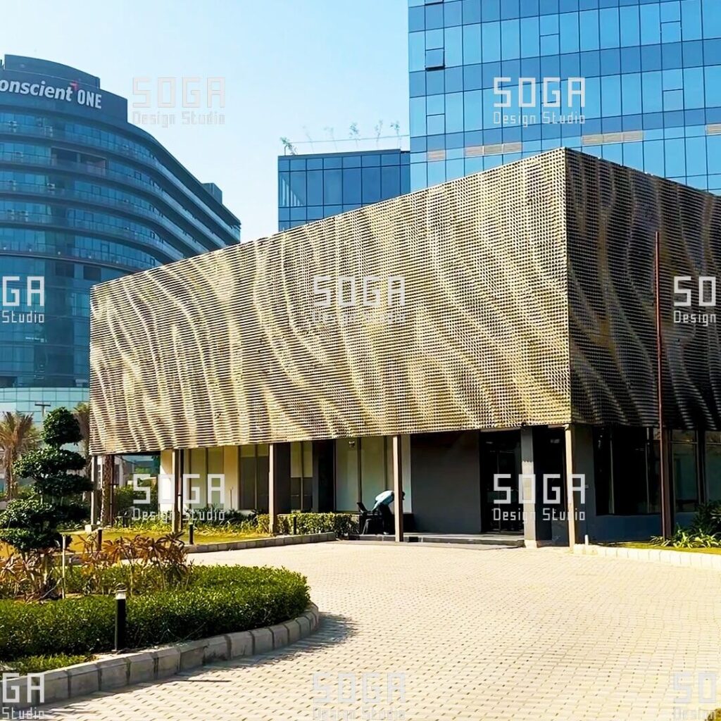
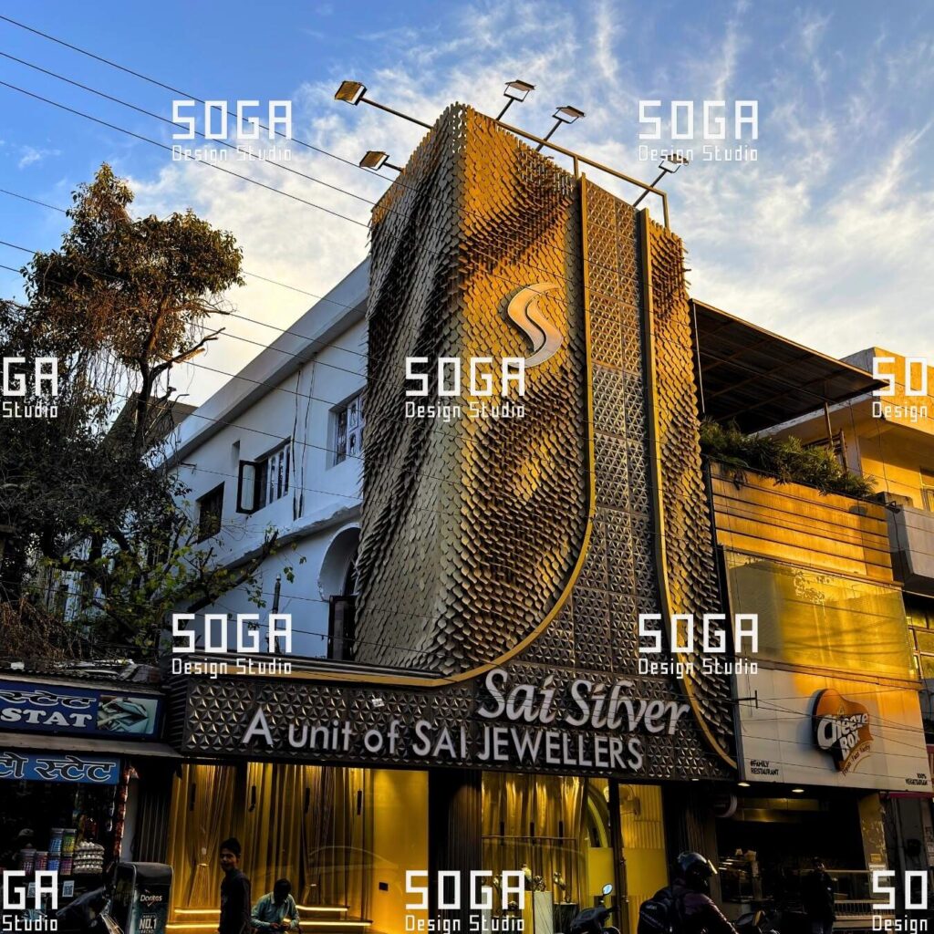
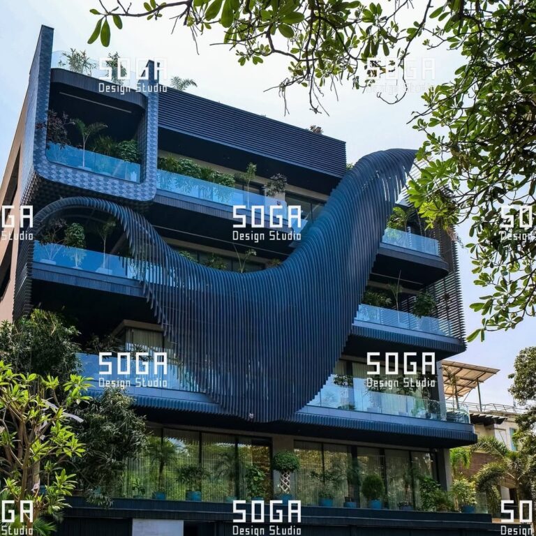
The other half of the problem is that no two fins are alike. A slicing fin facade is generated by cutting a three-dimensional surface into vertical sections, so each fin differs from its neighbour by a small, ruled amount. A flat wall built this way reads as curved, or twisting, or swelling open around an entrance. The surface itself is not there; only its sections are.
The SOGA Slicing Fin Facade is a slicing fin facade system developed by SOGA Design Studio for Indian fabrication. What follows is written from that development rather than from a survey of the category: the profile trials, the straightness testing and the bracket work that decided how a slender fin is kept true between the cutting bed and the scaffold.
It is also a shading device before it is a pattern. Depth, spacing and rotation follow from sun geometry at a specific latitude and orientation, and the visual effect is whatever those numbers produce. Reverse that order and the elevation shades nothing in particular.
A slicing fin facade is a vertical shading system in which each fin varies in depth, angle or profile along the elevation, so the facade appears to open and close as the viewer moves. Fins are cut individually from a parametric model, restrained top and bottom, and set out against a controlled straightness and alignment tolerance.
What “slicing” means in a fin facade
Slicing describes a method of generation, not an appearance. A conventional louvre facade takes one profile and repeats it. A slicing facade starts from a driving surface — a curve in plan, a twist rising up the building, a swell around an entrance — and cuts it into vertical sections at the fin spacing. Each fin is one section, stood on edge.
A slicing fin turns about the vertical axis, which is what an east or west wall asks for. On a south wall the same extrusion should be laid flat and tilted instead – when to use a horizontal louvre instead.
A flat wall carries the reading of a curved one. The surface exists only along the outer edge line of the fins. Move off the perpendicular and several fins fall within one glance, their edges line up, and the eye reconstructs the surface between them. Seen straight on, the same fins collapse to thin lines and the surface disappears.
The fabrication data is generated rather than drawn. Fin 47 is not designed. It is what the surface produces at position 47, and profile, length, rotation, taper and restraint heights all fall out of one model. The eye also learns the progression within a dozen fins, so abandoning the surface locally — to clear a column, to dodge a downpipe — is detected immediately.
Fin geometry: depth, chord, taper and twist
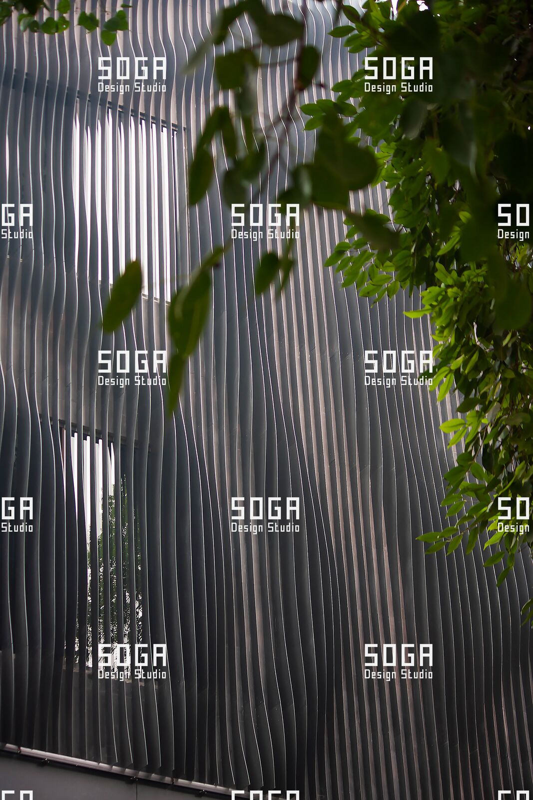
Six parameters describe nearly every fin in this family, and they differ sharply in cost.
Depth is the dimension standing off the wall. With spacing it sets the shading cut-off, and it sizes the bracket, because wind across the fin face returns as a couple with depth as the lever arm.
Chord is the developed width of the face, equal to depth only on a flat fin normal to the wall: depth governs performance, chord governs consumption. Taper is depth varying along the length, and a fin tapering towards a restrained end loses section where the moment is highest.
Rotation is the angle of the fin about its vertical axis. It has the largest effect on shading and view of any parameter and is the cheapest to vary, because it changes nothing about the part — only the bracket.
Twist is rotation varying along the length. It is where the surface reads as three-dimensional and where the risk sits, because it needs a forming operation on a slender part. Edge profile decides whether the fin reads as an object or a cut sheet, and a returned lip buys torsional stiffness cheaply.
| Parameter | Range considered | Shading effect | View effect | Fabrication cost effect | Install effect |
|---|---|---|---|---|---|
| Fin depth | From the cut-off, against bracket moment | Sets cut-off with spacing | Closes oblique view both ways | Heavier part and bracket | Heavier lift |
| Fin spacing | From the cut-off, against bays and access | Lower cut-off as spacing tightens | Sets the gap the eye measures | High; sets part count | High; drives install hours |
| Rotation angle | Bounded by the view retained | Cut-off turns asymmetric | One view kept, one lost | Low; same part, indexed bracket | Low; set by bracket |
| Taper | Bounded by the minimum useful section | Minor; varies with height | Alters perspective | Affects nesting yield | Low, if marked |
| Twist | How far the surface turns per fin | Minor; varies up the fin | Surface reads as turning | High; a forming operation | High; two angles per bracket |
| Edge profile | From the defined family | Negligible | Object or cut sheet | A fold that buys stiffness | Low; survives handling |
Why every fin can be different without every fin being unique
A fin is different when its geometry differs from its neighbour’s. It is unique when producing it needs a different setup — a different nest, tool, forming operation or inspection routine. Difference is close to free. Uniqueness is expensive in steps: two hundred profiles cut from one nest at one machine setting cost far less per part than four batches of fifty, because the cost lives in stopping and resetting. So push variation into parameters that do not change setup: rotation first, then length, then depth within a single cutting family, and only then twist.
Then rationalise the progression. A continuous surface produces a continuous range of depths and no shop floor needs one. Quantise it into a family of profiles and let the steps do the work, because the eye reads the trend rather than the increment. To size the family, stand two adjacent members at the real viewing distance in raking light: if the step is invisible, the family is large enough. SOGA fixes the profile family that way before an elevation is issued, because a family agreed on a screen and a family that survives raking light are rarely the same one.
Fin schedule fields required for fabrication
The fin schedule carries the facade from model to shop floor, and fails by being incomplete. Each row carries:
- Fin identification number, with elevation and bay reference
- Setting-out coordinates top and bottom, against a level datum
- Overall and cut length, and depth at bottom, top and each restraint
- Rotation angle at bottom and at top, so twist is explicit
- Profile and edge type, material thickness, finish and exposed face
- Bracket type and restraint positions, from a stated datum end
- Which end is fixed and which is free to slide
- Orientation mark, position code and packing sequence
The two fields most often absent are the fixed-and-sliding designation and the orientation mark, and both cause expensive site problems. Fin depth is only half the decision — sizing a fin screen against the sky, not only the sun shows the same 45.0% free area returning between 1.3% and 35.8% of the daylight, depending on where that depth sits.
The support system
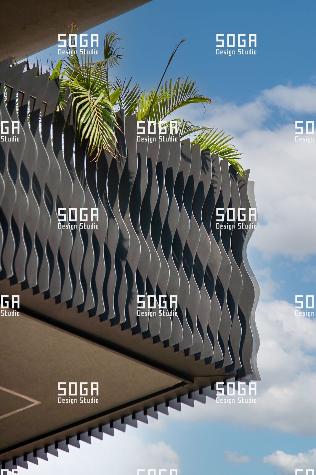
A fin is carried vertically at one point and restrained laterally at every other point. Keeping those roles separate is the whole of the support design, and merging them is the commonest structural error in the system. A fin hung from its top end is in tension along its length, and tension holds a slender element straight; a fin stood on its bottom end is in compression, which does the opposite. Every other bracket is a lateral restraint and must not grip the fin vertically. Clamp a fin at both ends and thermal expansion has nowhere to go: the fin lengthens and bows between its fixings — on every fin in the row, at the same time of day, which makes it unmistakable from the street.
Wind returns to the wall as shear and moment at each restraint, and where the fin is rotated it also applies torsion — which governs slender fin design more often than bending.
Top and bottom fixings, intermediate restraint, deflection control
Torsion is where a fin facade is won or lost. An open section — a plate, an angle, a channel, a folded profile that does not close on itself — has very low torsional stiffness, and that stiffness scales with the cube of material thickness. Halve the thickness to save weight and roughly seven-eighths of it goes. Closing the section into a box, or returning a lip along the free edge, multiplies it for little material. A fin that will not hold its angle is asking for a closed section, not more brackets.
Restraint spacing is decided against four criteria, which rarely agree.
- Strength. Stress under design wind pressure, which seldom governs on fins of ordinary proportion.
- Serviceability deflection. A span ratio plus an absolute limit, the absolute limit mattering more, because the fin must stay clear of the glass line and its neighbours under load.
- Visual deflection. Stricter than either, and almost never specified: a fin deflecting more than its neighbours breaks the rhythm of the gaps read against the sky. No code supplies a value, so the limit has to be adopted for the project, written into the specification, and designed to.
- Dynamic behaviour. If a fin’s natural frequency sits near the shedding frequency at a common site wind speed, it will oscillate there and keep doing so.
The maximum unrestrained span satisfying all four belongs to the profile in use, not to fin facades in general, and it has to be derived for that profile rather than borrowed from another project. Beyond that an intermediate restraint is needed — though adding restraints does not automatically improve straightness, because every restraint transfers the substructure’s errors into the fin. A fin held at two accurate points is straighter than one held at six, three of them wrong.
The bracket does two jobs usually kept apart: it absorbs the building, and it sets an angle. The base part fixes to the structure with adjustment in three axes over a stated range, checked against the deviation the frame is actually being built to, then aligned to a surveyed line and locked. The upper part receives the fin, and its angular geometry is a manufactured feature rather than a site measurement: a serrated seat, a keyed spigot, a machined flat that accepts one angle and refuses every other. The angle then arrives from the workshop, and no jig has to survive a working site. This was the constraint that shaped SOGA’s approach to the bracket: rotation is the cheapest parameter in the system only if setting it costs the site nothing.
Shading and glare behaviour
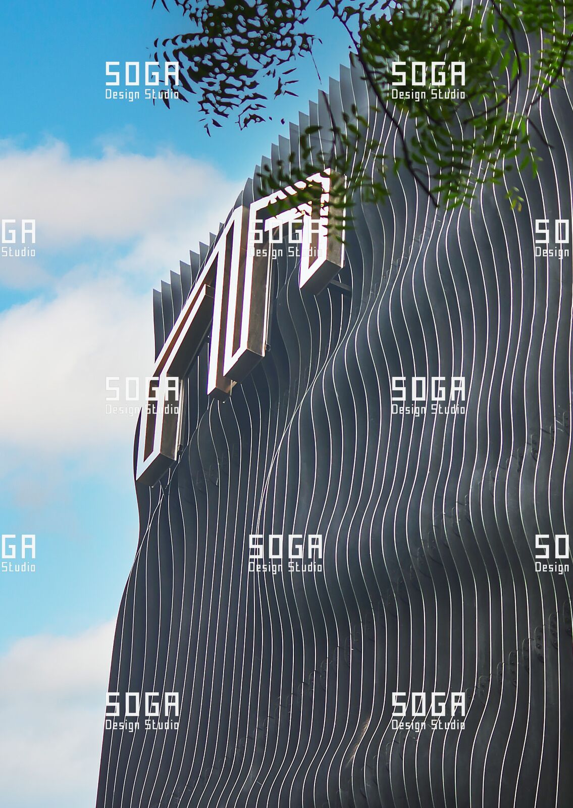
Vertical fins intercept sun arriving at a wide angle to the facade normal, and do very little about sun arriving close to normal, whatever their depth. The governing quantity is the horizontal shadow angle: the angle in plan between the sun’s azimuth and the facade normal. Fins work when it is large — early morning on an east elevation, late afternoon on a west one, when the sun is low and sweeping almost parallel to the wall.
For fins perpendicular to the wall, the cut-off angle is the arctangent of clear spacing divided by fin depth, measured from the normal, and beyond it the sun is fully blocked. Deepen the fin or narrow the gap and the cut-off falls, which means more shading. The same number governs the view: an arrangement that closes against afternoon sun on a west elevation closes the afternoon view by as much. Rotation turns that trade-off into a choice, because rotating fins about their vertical axis makes the cut-off asymmetric — closed towards the sun’s approach, open the other way. The occupant keeps one view and loses the other, which is a decision taken with the floor plan on the table.
Deriving the cut-off is a method rather than a lookup. Take the actual latitude and orientation, build the sun path for the year, and overlay the hours when the space is occupied and cooling is being paid for. Identify the azimuth band carrying the direct beam in those hours, set the cut-off to close it, then check what view it has cost. An angle borrowed from another latitude is wrong invisibly, until the first summer.
The cut-off fixes a ratio, not a pair of numbers. Deep fins at wide spacing and shallow fins at close spacing give the same cut-off and have nothing else in common: close spacing multiplies part count and cleaning difficulty, deep fins multiply bracket moment and handling weight. A related question is how many louvres a floor actually needs, which the same cut-off ratio answers floor by floor as exposure changes up a building.
Glare is a separate problem from solar gain. Fins handle direct beam glare well and do very little about the diffuse glare of a bright overcast sky, which arrives from the whole dome. They can also become glare sources: a specular inward face lit by low sun is sometimes worse than the sun it blocks, and the answer is a diffusing finish rather than more depth. Because fins intercept the beam outside the glass they reduce cooling load rather than redistributing heat already inside, so ask for annual beam interception by orientation.
Orientation-driven angle strategies
Each elevation is a different problem, and treating them identically over-shades one and under-shades another.
| Orientation | Sun geometry to manage | Fin strategy that follows | What fins cannot do here | Failure if applied without study |
|---|---|---|---|---|
| East | Low sun, wide sweep, before peak load | Moderate depth, rotation closed to the morning sun | Anything once the sun is high | Over-shading gain that arrives before the building warms |
| West | The same geometry mirrored, after heat has accumulated | Deepest fins, lowest cut-off, rotation closed hard | Remove heat already stored | Detailing the west to match the east |
| South (northern hemisphere) | High sun near the normal all day | Fins for continuity; a horizontal element for high sun | Block a near-perpendicular beam | Claiming a benefit the geometry cannot give |
| North (northern hemisphere) | Small exposure at the ends of the summer day | Shallow fins or none; continuity, not gain | Reduce diffuse sky glare | Paying for shading that is decorative |
| Corners and returns | Angles change continuously; local pressures highest | Transition rotation across bays; heavier end brackets | Hide an abrupt change of strategy | Two designs meeting at an arris |
Fabrication constraints that shape the design
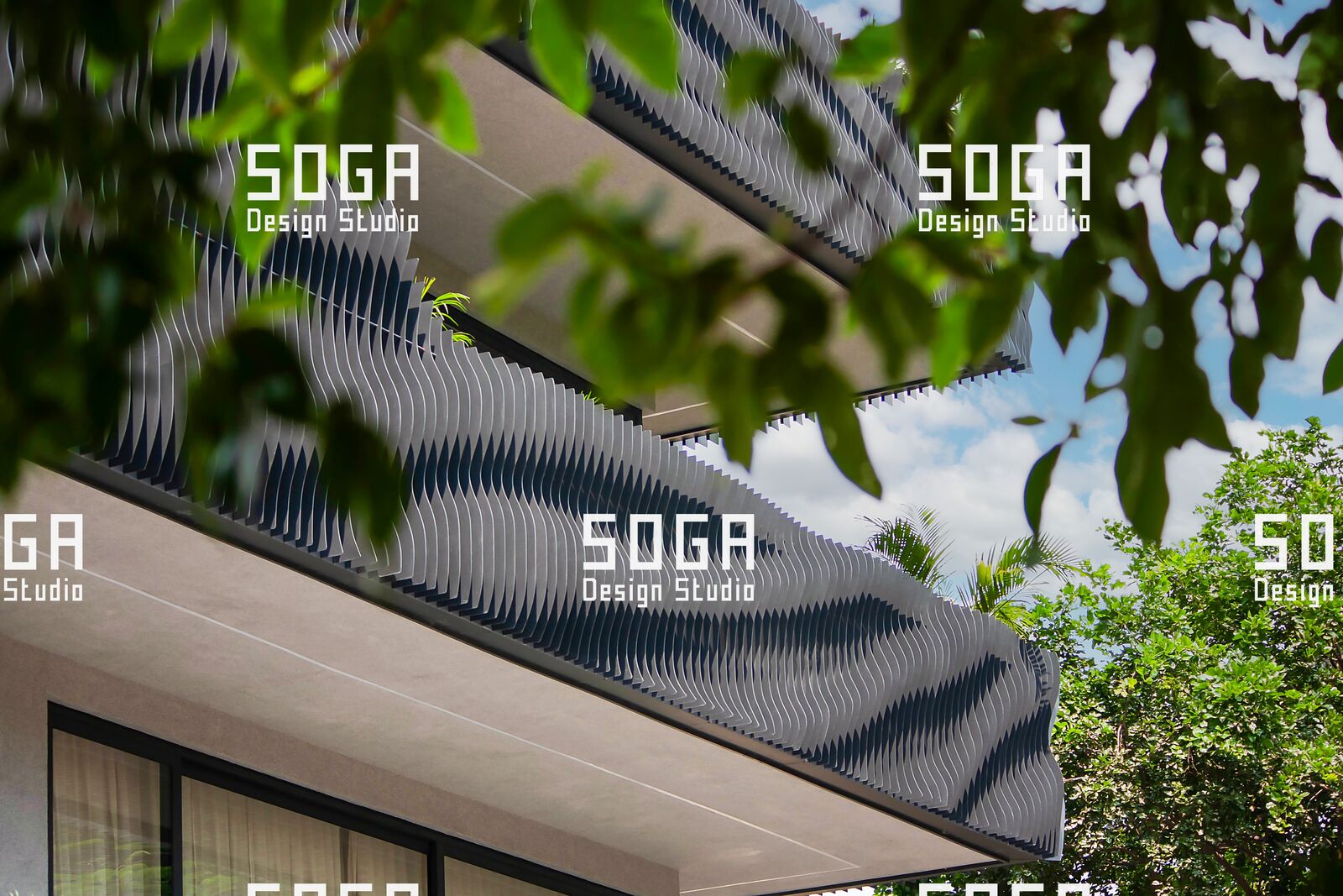
Long thin parts move, and most of the fabrication discipline here is about controlling when they do.
Stock carries locked-in stress. Material arrives with residual stress from its own production, and while the stock is whole that stress is in balance. Cut a slender tapering profile out of it and the balance breaks: the section relaxes as bow, camber or twist, so a part cut accurately is now the wrong shape. The response sits in the cutting strategy — nesting so stress releases symmetrically about the part’s own axis, retaining tabs so the fin is not freed in one moment, sequencing cuts so release is progressive. SOGA settled that sequence during fabrication trials, on a production floor and at full part length, because stress release at sample length is not what it is at the length a facade actually uses.
Forming adds a second error. A fold or returned lip introduces plastic strain along the length. If the bend angle varies end to end, because thickness varies within tolerance or springback differs along the tool, the result is not a slightly wrong fold. It is a helix, and the part twists progressively — precisely the deviation the eye detects best.
Plant and handling set the rest. Ovens impose a maximum part length, so longer fins are spliced at a restraint, at one height across the elevation. A fin stored flat on uneven supports takes a set, so racking, lifting points and packing belong in the fabrication package.
Straightness is a specified quantity, not an aspiration. State it as a permitted deviation over the fin length, and state the method with it: against a bench or a tensioned wire, recording bow and end-to-end twist separately, because they have different causes and different fixes. Verify after finishing, because heat in the finishing line releases stress that cold straightening had removed. A tolerance not measured before despatch will be measured by the client, from the pavement.
Installation: alignment, straightness, and the eye’s tolerance
The eye judges a fin facade by comparing each fin against its neighbours, which makes perception tolerance tighter than fabrication or structural tolerance. A twist of a degree or two, which no structural check would flag, is therefore a defect. Three mechanisms combine. The eye reads a repeating pattern as a periodic signal and is far more sensitive to a break in periodicity than to an absolute dimension — nobody perceives the spacing, everybody perceives the one gap that differs. A fin is also a light-reflecting plane whose brightness depends on its angle to sun and viewer, so a twisted fin carries a brightness gradient its neighbours do not. And foreshortening amplifies the error, because a fin’s visible width seen obliquely is a function of its rotation.
The practical response is to decide which lines the eye will read and make only those perfect: fin tops against the sky, fin bottoms against a soffit, and the rhythm of gaps at eye level. Deviation elsewhere is absorbed and never noticed.
Fins are set to an independent survey line running the length of the elevation, taken from an as-built survey rather than the drawing, because working cumulatively bay to bay delivers the accumulated error to the corner bay everyone photographs. Brackets go up across the whole elevation and are checked as a set before any fin is hung, since a bracket line out by a small amount is adjustable while empty and expensive once loaded.
Two site errors account for most remedial work. The first is a fin installed in the wrong position, subtle enough to survive the scaffold and obvious from the ground afterwards; position marks, packing in sequence and a bracket that refuses the wrong part are the defences. The second is an attempt to correct a twisted fin in place. That is not a repair: a section that has taken a set will not be persuaded back on a scaffold, so the fin is replaced. In the version SOGA develops, single-fin removal is therefore detailed before the pattern is, rather than after.
Acoustic, wind and maintenance considerations
Fins make noise under three conditions. Shedding tone comes from air separating at a bluff edge and shedding vortices at a frequency proportional to wind speed; when that approaches a fin’s natural frequency the fin resonates and radiates a tone at one wind speed and direction, which is why the complaint arrives months after handover and is initially disbelieved. Change the frequency through restraint spacing, or profile the edge so separation is not coherent. Gap whistle comes from air accelerating through a narrow, sharp-edged gap, and uniform spacing strengthens the tone because the sources stay coherent. Knock comes from a restraint loose enough to move, and a resilient interlayer solves it.
On wind loading, the case that catches projects is not peak pressure at mid-elevation. It is local suction at corners, parapets and free ends: the first and last fin in a run see higher loads than the field, and designing the whole elevation to the field value produces failures where the building is most visible.
Maintenance is usually settled after the system is priced, which is too late. Fins obstruct facade access, so a cradle needs stabilisation that does not bear against them, and whether a cleaner can reach the glazing behind is set by the clear gap — the same number the sun study fixed. Upward-facing surfaces collect dust, which the first heavy rain carries down the wall behind.
Slicing fins vs other shading options
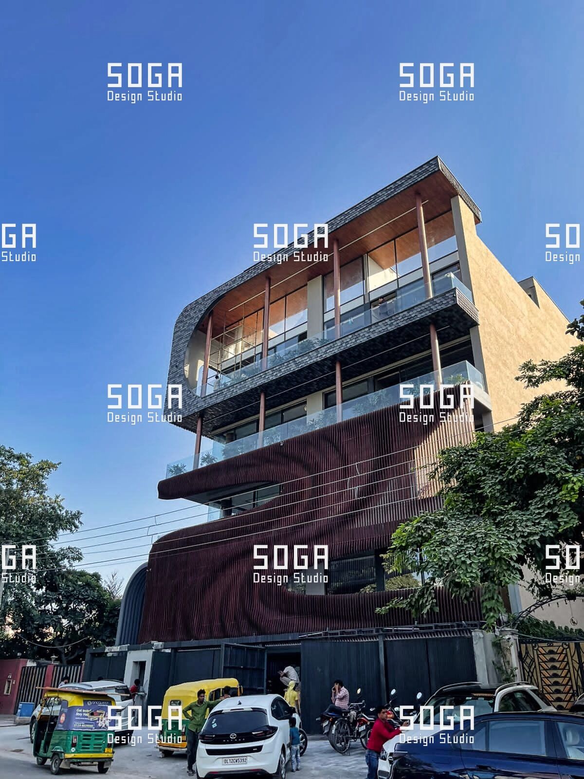
Fins are one of several ways to keep sun off a glass line, and are the right answer less often than they are proposed. Against high-performance or fritted glazing, fins cost more, weigh more and need maintenance. What they offer is direction: glass reduces transmission equally from every angle, including the daylight a building wants to keep, while fins close one azimuth band and leave the rest alone.
Against horizontal shades and overhangs, the comparison is pure geometry: fins win on east and west, where the sun is low and wide of the normal, and overhangs win on south, where it is high and near normal. A building needing both ends up with an egg-crate or a strategy that changes by elevation.
Against perforated screens, fins preserve a far better view for the same shading, because a screen blocks the same proportion of view in every direction. Against internal blinds, they intercept the beam before it reaches the glass rather than after the energy is inside. Against operable louvres, they have no motors, no controls and no failure state, and cannot respond; an operable system carries a lifetime obligation better priced at selection than at the first actuator failure.
How to brief a slicing fin facade
These questions separate a fin system from a fin drawing. Ask them before the elevation is fixed, because the answers change it.
- What is the driving surface, and does every fin derive from it? If fins were adjusted individually, the progression breaks visibly.
- How many fabrication setups does the facade need? Not how many fins. Setups.
- How was the cut-off angle derived? Look for a sun study at the actual latitude and orientation, weighted to occupied hours — not an angle carried over from another project.
- Is the section open or closed? If it is open and the fins are long, ask what stops them twisting.
- What is the maximum unrestrained span for this profile, and which criterion governed it? The answer should name one, often the visual limit.
- Which end is fixed and which slides? If nobody can say, the fins will bow.
- What straightness tolerance will fins be measured against, and when? After finishing and before despatch, by a stated method.
- How does the bracket set rotation, and does it need a jig on site? A manufactured angular interface is the only answer that survives a working site, and the base bracket absorbs structural deviation.
A proposal answering all eight is a system. Fewer than five and it is an elevation drawing with fins on it.
How SOGA developed this system
The problem that started the work was straightness. A slicing fin facade asks a long, slender element to arrive at the scaffold as straight as it left the model, and little in the process allows it. Cutting a tapering profile out of stock releases the stress locked in it, so the part relaxes as bow or twist. The finishing line then returns the deviation that cold straightening had removed. A fin wrong by a degree of twist passes every structural check and is legible from the pavement.
The work ran as a loop. Prototypes set open sections against closed ones. Fabrication experiments took nesting, cut sequencing and the finishing line onto a production floor at real batch lengths, which is where most of the drawing changed. Structural studies covered torsion rather than bending, because torsion governs a rotated fin. Installation testing built a mock-up in the order a site works. Manufacturing optimisation followed once the profile family was fixed.
Two things changed between the first prototype and the production system. The first was the section. The prototype answered twist with more restraints, which made it worse: every added bracket transfers another substructure error into the fin. The production profile closes the section, or returns a lip along the free edge, and the restraint count comes down. The second was the bracket. The prototype set rotation by site measurement against a jig, which survives a mock-up and does not survive an elevation. The production bracket separates the jobs: the base part absorbs structural deviation in three axes and locks to a surveyed line, while the upper part carries a manufactured angular seat that accepts one angle and refuses the rest.
Development ran within the six-months-to-a-year range the studio’s systems take.
It is manufacturable in India because every operation it needs — cutting, folding, welding, finishing — is one Indian shops run daily in long batches.
SOGA Design Studio is a parametric and computational architecture practice based in Gurugram, working across India, Dubai and Singapore, specialising in facade systems engineered for local fabrication.
Frequently asked questions
Do slicing fins reduce daylight inside?
They cut direct sun and beam glare while leaving diffuse daylight and the view normal to the facade largely intact. The balance is set by fin depth and rotation angle together, not by spacing alone.
How are fins kept straight over long spans?
Straightness comes from three things: a section stiff enough in torsion, intermediate restraints spaced from the profile rather than the substructure, and a fabrication straightness tolerance stated as a permitted deviation over the fin length. That tolerance is verified after finishing, because heat in the finishing line releases stress that cold straightening had removed.
Can fins be angled differently on each floor?
Yes. Angle can vary per fin, per bay, per floor or per orientation, and it is carried by the bracket rather than the part. That is the central reason to use a parametric fin system instead of a standard louvre: rotation is the cheapest parameter available and the most effective.
Are slicing fins only for offices?
No. They suit any elevation needing directional shading with visual depth, including institutional, hospitality and larger residential buildings. Orientation and facade access matter more than the building type.
What decides whether a fin facade works
A slicing fin facade presents itself as a problem of pattern and turns out to be a problem of restraint. The engineering that matters is the section that stops a slender element twisting, the cutting sequence that lets a part relax without leaving its tolerance, the sliding end that lets a fin grow on a hot afternoon, and the bracket that carries an angle out of the workshop. None of it is visible in the finished building.
The failures are predictable in the same way. Fins bow because both ends were fixed. They twist because a slender open section was thinned to save weight, or a fold varied along its length. The elevation reads as arbitrary because the driving surface was abandoned at a column, and the shading disappoints because the cut-off was inherited rather than derived. Each is a design-stage decision, cheap to settle early and expensive once the first crate is on site.
The system was worked out in India and engineered here, against Indian stock, Indian shop floors and Indian frames, rather than adapted from a system built elsewhere. It carries abroad for the same reason it holds at home: nothing in it depends on a straighter frame, a steadier hand or a longer programme than the ones it was designed against.
Fin schedules and bracket details from our system development are available if you are sizing fins against a real elevation.
Depth also decides how a fin’s depth sets the note it plays in wind: a 25 mm fin sheds at 120 Hz at 15 m/s, a 230 mm fin at 13 Hz and is inaudible.