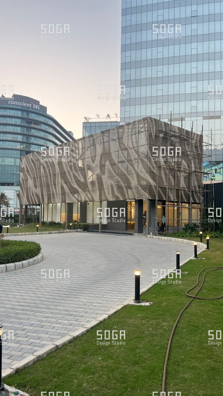
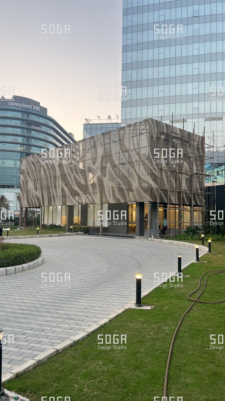
Coin facade installation is mostly not the installation of coins. The discs go on late and they go on quickly, and by the time the first is hung, almost everything deciding how the elevation reads is already fixed — in the survey, in the bracket settings, in the lines the carrier was set out to.
A coin facade is installed as a carrier first and a disc field second. Disc geometry, pattern and load path belong to the complete coin facade guide; blanking, forming and sub-assembly to how coin panels are manufactured, which ends with packed crates. This one begins at the gate.
The SOGA Coin Facade is a coin facade system developed by SOGA Design Studio for Indian fabrication, and the sequence below is the one the studio settled on through installation mock-ups and site work.
Coin facade installation begins with an as-built survey of the structure, followed by setting out and levelling the carrier system, then hanging pre-assembled panel modules in a planned zone sequence. Adjustable brackets absorb structural deviation, and alignment is checked by line and level at every bay before the next zone starts.
Installation starts with the survey, not the panel
The frame that gets built is not the frame that was drawn. Slab edges wander, columns lean within their permitted band, and cast-in channels move when concrete goes in around them. That is what a concrete frame is allowed to be, and the facade is the trade that absorbs it.
So the first operation is measurement, and it happens before a crate is opened. The facade installation site survey records what the structure delivered where the facade will touch it: insert positions, slab edge line and level, column faces, opening reveals, and anything already fixed in the bracket zone. It decides whether the brackets ordered are the brackets required.
Measuring the as-built structure against the model
Every reading must trace back to one benchmark and one grid line that the main contractor, the surveyor and the installer all recognise; measuring each slab edge from the slab above gives consistent local readings and a facade that steps. The points are overlaid on the coordinated model, and the output is a deviation map by bay: where deviation sits inside what the brackets absorb, where it does not, and where two deviations of opposite sign meet in one bay and consume the whole range.
Two failures recur: the survey is run with a tape because the instrument survey was priced out, or it is run properly and never shared, so brackets get made against the model. The remedy is a named, dated deliverable ahead of bracket manufacture.
The tolerance conversation nobody has early enough
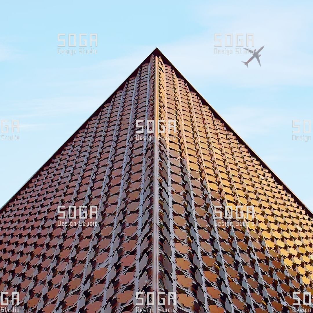
Facade tolerance in India gets discussed as a single number. It is a stack: the frame is built to a construction tolerance set by its own specification, the anchor lands within its placing tolerance relative to that frame, the bracket sits on the anchor with whatever its slots allow, the carrier runs between brackets, and the collar sets pitch and rotation at the end of the chain. Every interface takes a share of the movement, and each has a different owner. The stack fails wherever an owner was never told what they were carrying.
Structural tolerance vs system adjustability
Two ranges have to overlap with margin. Structural tolerance is what the frame is permitted to be, set in the structural specification long before the facade is procured. System adjustability is what the bracket can take out, set by the facade designer through slot geometry, packing provision and bracket depth. The comparison belongs on paper at design stage, against the specified frame tolerance. Where the ranges only just overlap, the facade fits on a good bay and not on a bad one, which is the same as not fitting.
SOGA states bracket adjustment axis by axis in the system drawings, because the axes are not consumed equally and the one that runs out first is rarely the one being watched. Whatever is spent at installation is also unavailable when a member later moves with temperature.
Adjustment allowance schedule by fixing type
| Fixing type | Axes it adjusts | What governs the range | How it is verified | When it runs out |
|---|---|---|---|---|
| Cast-in channel and bolt | Along the channel; packing out | Channel length; placing accuracy in the pour | Channel positions surveyed before brackets are released | Engineer-approved post-fixed plate, never a site weld |
| Post-drilled anchor | Free placement in an approved zone | Edge distance, spacing, reinforcement | Reinforcement scan; marked drilling zone | Relocation, or a redesigned plate |
| Bracket-to-carrier slot | In and out; up and down | Slot length, washer bearing, edge distance | Setting gauge; as-left position recorded | Packing from an approved range only |
Setting out the carrier system
Facade setting out is where the elevation is decided; everything after it is execution. The carrier is set to a control line derived from the survey and offset from the building grid, never off the slab edge, because the slab edge is one of the things that moved.
Order matters more than instruments. Extreme positions go in first: both ends of the elevation, the corners, and the control points where the facade meets a movement joint or a change of plane. Only then are the bays between them subdivided. Setting out bay to bay from one end delivers the accumulated error to the last bay, as a taper nothing can absorb because the discs are already made.
Two site conditions complicate this. Other trades reach the bracket zone first, a riser bracket sitting where a fixing is drawn, so an interface register closed zone by zone is worth more than another meeting. And a long carrier member measured in afternoon sun is not the same length at dawn, so checks run under comparable conditions.
The carrier is then surveyed and accepted as a complete plane before a single disc is hung. An empty carrier is adjustable by one person with a spanner; a loaded one is a dismantling job.
Panel sequencing and delivery batching
Each load is checked against the crate schedule with the transporter present: crate identity, zone code, count, and a condition check on rims and tags. Transit damage found later becomes an argument; found at the gate it is a replacement request with a photograph attached.
Two storage failures are specific to sites here. Urban plots rarely have the lay-down area the programme assumed, so crates spread over whatever ground is free and zone identity is lost; deliveries called off zone by zone fix that better than a bigger yard. The second is protective film, which bakes into the finish through a hot spell and stops releasing cleanly, so film removal is a scheduled step at a stated point.
Erection direction follows the access method: suspended access works downwards, scaffold and mast climbers upwards. A zone is completed vertically through its floors before the front moves sideways, so joins fall at planned lines and the access is paid for once. One rule overrides the rest — whatever sits behind the screen is signed off before the disc field goes on, because afterwards it is reachable only by taking part of the facade down.
Why panels are packed by zone, not by type
Sorting by type is how a factory thinks, and it is the worst way to send a graded field to site: crates of near-identical assemblies, and every fixing turned into a lookup at height with a code read through gloves. Packed by zone, a crate is a bay and a bay is a day’s work.
A crate opened out of sequence to find one missing assembly is rarely resealed correctly. Contents get redistributed, zone identity is lost, and the tone mapping planned during finishing is no longer what is installed.
Access strategy: scaffold, cradle, or mast climber
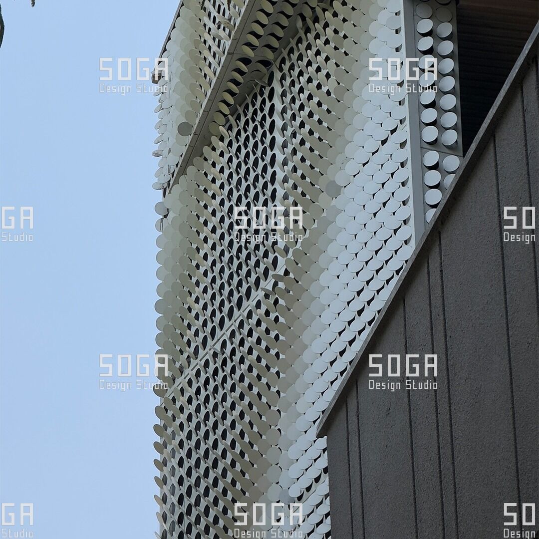
Access for a coin facade answers two conditions the choice is often made without. The field stands off the wall, so the platform must reach both the disc face and the carrier behind it without occupying the plane the finished discs will sit in. And a disc field offers no flat surface, so anything bearing against it bears on a formed rim.
Each method inherits a consequence. Scaffold ties pass through the facade plane, so tie positions are coordinated against the pattern and those panels are left out and installed last. Cradles need stand-off arrangements bearing on the carrier, never on the discs. Mast climbers give a deck the length of a bay, which suits carrier setting out, at the cost of base capacity and tie coordination.
| Access method | Suitable height band | Panel handling ease | Setup time | Cost impact | Site constraint sensitivity |
|---|---|---|---|---|---|
| Full scaffold | Low to mid-rise, bounded by ground bearing and ties | Best; continuous deck, materials at the face | Longest; on the critical path | High; driven by hire duration | High; ground area and coordinated ties |
| Suspended cradle | Mid to high-rise, where roof rigging is possible | Limited; small platform, awkward for long members | Short once rigging is installed | Moderate; rigging design is an early cost | High; wind, parapets, projections |
| Mast climber | Mid to high-rise, long repetitive elevations | Good; deck matches a bay, materials rise with it | Moderate; base and ties needed | Moderate to high; efficient on repetition | Moderate; dislikes stepped bays |
| Mobile platform | Low-rise and podium levels | Moderate; no staging at height, small teams | Shortest of the four | Lowest per day; poor value when tall | High; firm ground and clear perimeter |
Scaffolding is a choice here, not a default.
Working at height with small components
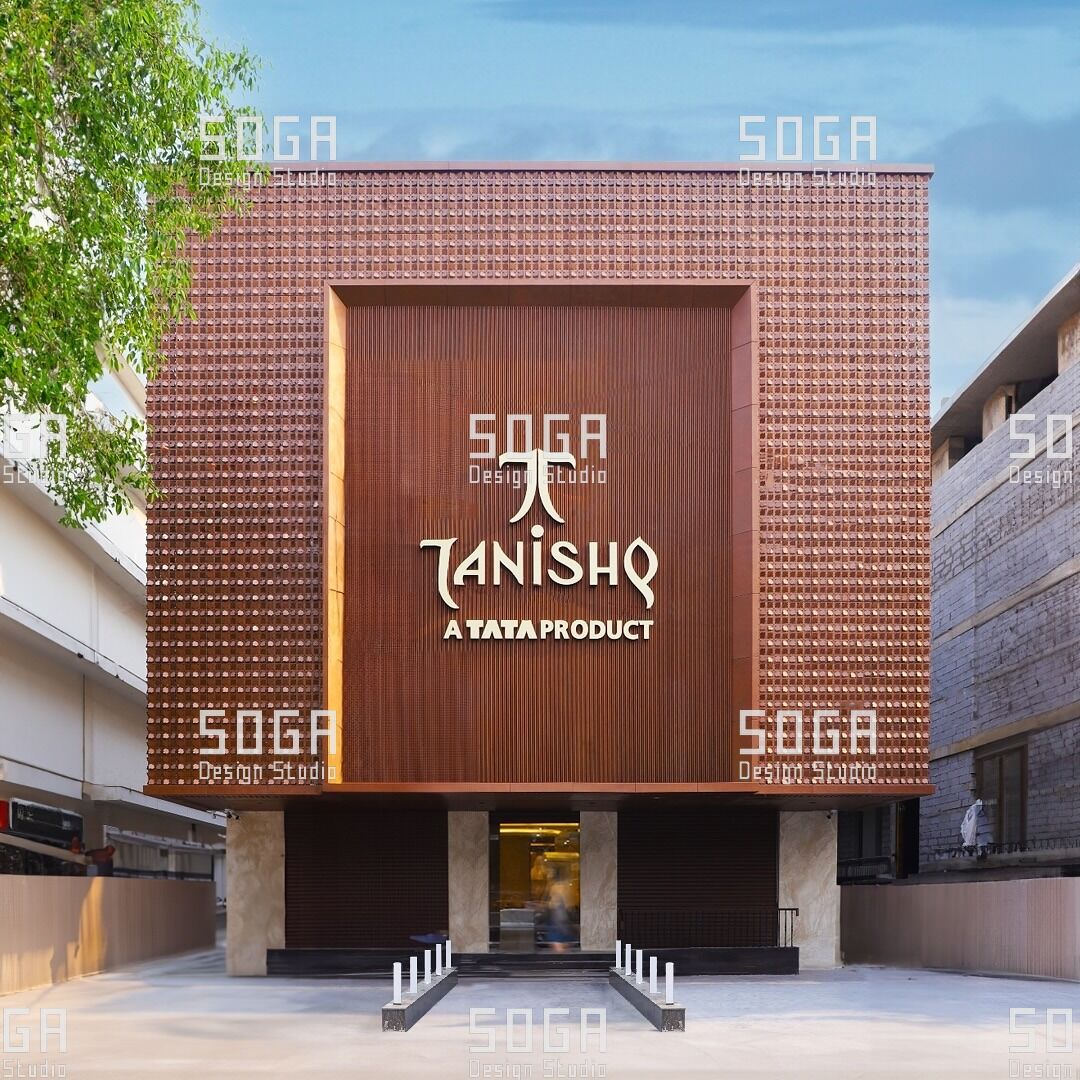
A coin facade multiplies small parts, and every disc brings a collar, a fastener set, an isolation component and a locking element, all handled by a gloved hand above a public area. Parts are issued as a per-bay kit against a check sheet rather than from a communal bucket, tools are tethered, and netting goes behind the carrier line as well as below it, where dropped fasteners collect.
Coin panel fixing at height is torque-sensitive work done in the worst conditions for it. Tightening uses calibrated tools on a stated sample-check regime, and the locking method has to hold without a re-check nobody will perform. Isolation components are the item most often omitted at height, and the fix is pre-fitting the isolation piece to the bracket at the bench, so the fixing cannot be completed without it.
Weather governs more of the programme than the drawings admit. A panel module is a sail, so a wind stop rule is agreed with the access supplier and written into the lifting plan as a condition read off an instrument, not a foreman’s judgement. Monsoon removes working days, and in the hot months the window shifts early, because members set out at peak surface temperature are set out long.
Alignment control and the human eye
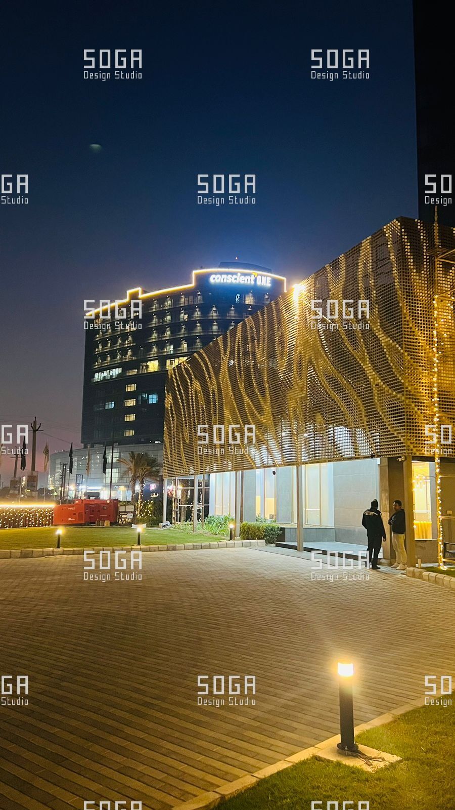
The eye reads a disc field in a particular way, and alignment control should be aimed at what it reads: the alignment of disc centres along the lines of the field, the consistency of the gaps, the silhouette against sky, and the line where the field stops at an opening. It forgives deviation perpendicular to the facade plane, for the reason the pillar guide sets out — between separated circular objects a small step in depth does not register.
So the checks are line checks, made against the datum and never against the neighbouring disc: setting each disc to the one before it accumulates drift in one direction and closes the field up across an elevation. A raking-light inspection at low sun catches what midday cannot — an assembly rotated off its datum, a rim sitting proud, a line curving gently over several bays.
Two problems come from crew organisation. Teams starting at opposite ends of an elevation deliver their combined difference to the bay where they meet, so the meeting point is planned at a corner or a joint before either starts. A crew working fast also tightens the gap as it goes, invisible bay by bay and obvious across a floor.
Snagging, replacement and handover documentation
Snagging is defined by viewing condition — the distance, lighting and angle stated in the specification — or it is defined by whoever holds the list. Without that condition the list carries marks visible only from a cradle and misses a tone step visible from the road.
The cost of replacing one disc is not the disc; it is the access. A snag closed while the platform is at that zone costs an hour; the same snag after demobilisation costs a re-mobilisation, so snags are raised and closed zone by zone. Single-disc replacement is a procedure rather than a claim: the assembly releases at its collar, outwards, leaving neighbours undisturbed, and that release direction belongs on the handover drawings.
| What goes wrong | Where it originates | When it is caught | How it is prevented |
|---|---|---|---|
| Carrier line drifting off datum | Set out bay to bay, not from control positions | In the last bays, after discs are on | Extremes set from the corrected datum, then subdivided |
| Adjustment consumed at first fit | Deviation absorbed wherever it appeared | At the first thermal cycle or replacement | Brackets set toward mid-range; positions recorded |
| Rim marks and scuffed collars | Slings bearing on the rim; crates opened out of sequence | Snagging, often after access has moved off | Fabric slings clear of the rim; edge protection kept on |
| Missing isolation components | Fitted loose, by hand, at height | Year two, as staining below fixings | Isolation pre-fitted to the bracket at the bench |
| Tone step at a zone boundary | Crates re-sorted after an out-of-sequence delivery | First low-sun view from the street | Zone identity kept on crates; ordered call-off |
Handover is a document set, and what matters are the items nobody can reconstruct later: an as-installed survey of the carrier plane, torque records by zone, bracket as-left positions, a position code map, a batch map linking those codes to finish lots, and the drawing showing how one disc comes off. The batch map is the one whose absence turns a later replacement into a visible patch.
A realistic coin facade installation programme
Duration gets answered badly, usually by dividing panel count by an assumed daily rate. Facade installation sequencing does not behave that way, because the two halves of the work have different shapes. Carrier setting out is slow and front-loaded, largely independent of how many discs the elevation carries, governed by survey completeness, anchor accessibility and the number of interfaces to resolve. Disc hanging is fast and scales almost linearly, provided crates arrive in sequence and the carrier has been accepted. The shape that works is a rolling front, the carrier two zones ahead of the discs.
Rates are measured, not assumed. The first zone always runs slower than those after it, because the crew is calibrating a sequence rather than repeating one, and the response is to measure it and re-plan the remainder against it. SOGA’s installation mock-ups exist partly for this: a rate measured on a mock-up built the way a site builds is something a programme can be written against.
What actually delays this work is rarely the panels. It is a survey arriving after brackets were ordered, structure handed over incomplete, deliveries that lost their zone identity, access shared with another trade, and monsoon days left out of the baseline. Each has an owner, and the programme naming the owner beside the activity survives a live site.
How SOGA developed this installation method
The problem that started the work was the gap between what a frame is allowed to be and what a disc field will tolerate. A concrete frame here is built to a tolerance entirely reasonable for a concrete frame, while a regular field of circular objects read against the sky shows drift no frame specification cares about. Early disc fields were installed the way panelised cladding is, bay by bay with discs following the carrier crew, and the accumulated difference reached the end of the elevation with nothing left to absorb it.
SOGA developed the sequence by building it. Installation mock-ups were erected the way a site erects, with deviations deliberately introduced at the anchor positions so the brackets were asked to absorb what a real frame hands them, and crews were timed rather than asked. Structural studies covered the bracket under eccentric load, fabrication trials fixed the collar and the release direction, and manufacturing optimisation followed once packing had to match the erection sequence.
Two things changed between the first site and the settled method. The first was a sign-off gate: discs originally went up behind a rolling carrier front, which made every carrier correction an unloading job, and the carrier is now surveyed and accepted as a complete plane before any disc is hung. The second was the position of the survey, which began as a check performed on arrival and now sits ahead of bracket manufacture, so packing is known before brackets are made and adjustment is held in reserve rather than spent wherever the first crew found it convenient.
Development sat inside the six-months-to-a-year range the studio’s systems generally take. It works here because it asks for nothing an Indian site does not already have: an instrument survey, ordinary access equipment, and a sequence disciplined enough that the difficult decisions are taken on paper rather than on a deck.
SOGA Design Studio is a parametric and computational architecture practice based in Gurugram, working across India, Dubai and Singapore, specialising in facade systems engineered for local fabrication.
Frequently asked questions
What structural tolerance does a coin facade need?
The system absorbs frame deviation through adjustable brackets, and the range required is set by the tolerance the frame is actually being built to rather than by a standard figure. Where the survey shows deviation beyond what the brackets can take, packing to an approved schedule or a redesigned fixing is used, with the engineer’s approval.
Is scaffolding always required?
No. Access is selected against building height, assembly weight, elevation articulation and site constraints, and cradles, mast climbers and mobile platforms all suit particular cases. What matters more than the method is that the platform reaches both the disc face and the carrier behind it, and that nothing bears on a formed rim.
How is misalignment corrected after installation?
Individual assemblies can be re-shimmed or re-hung without dismantling adjacent zones, which is why the sequence starts from a verified datum line and why brackets keep adjustment in reserve. Correction afterwards costs access rather than components, so misalignment is closed zone by zone while the platform is there.
What most commonly delays facade installation?
Late structural surveys, deliveries arriving without their zone identity, and interfaces with other trades that were never assigned to anyone. The panels are rarely the constraint: by the time they reach site they are a repetitive operation on a carrier already accepted.
What the site actually decides
The discs are the visible part and the least of the difficulty. They go on quickly because everything ahead of them was done slowly. The same holds when a disc field goes onto a building already standing, where the survey carries more weight still — the subject of facade retrofit across India, Dubai and Singapore — and it governs how the field behaves once the wind is on it, covered in wind load and vibration in coin facades.
This method was worked out on sites here, against frames built to Indian tolerance, with Indian access equipment, Indian trades working above and monsoon inside the baseline rather than among the excuses. It needs no straighter building anywhere else, which is why it travels unchanged.
Installation sequence drawings and tolerance schedules are part of every system handover, and can be reviewed before you tender.