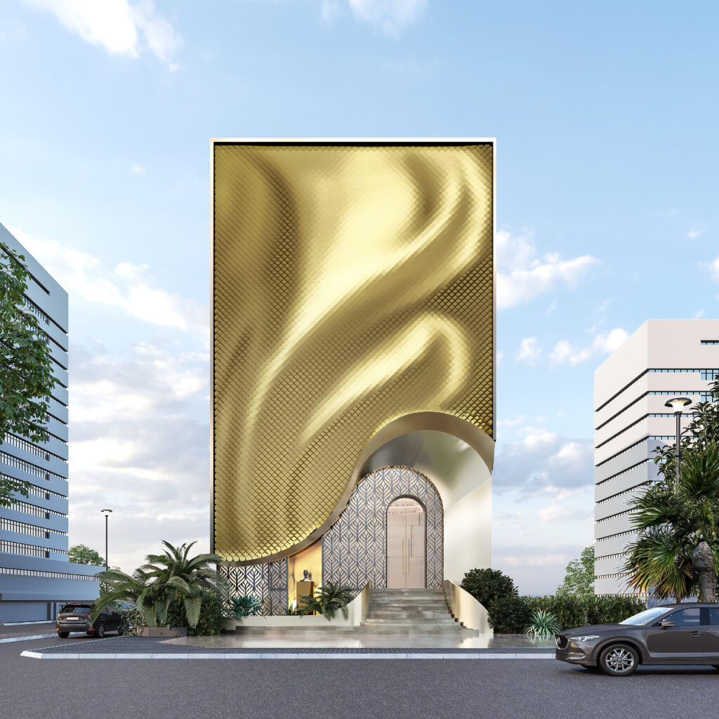
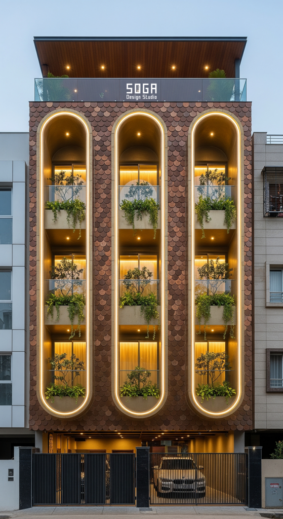
A parametric facade does not travel straight from a 3D model to an installed wall. Between the computational design model and the finished elevation sits a fixed sequence: a structural check, panel rationalisation into buildable families, a fabrication-ready CNC file, cutting and forming on the shop floor, finishing and transport, and a site installation pass with its own tolerance checks. On an Indian project, where fabrication capacity and the contractor’s own site tolerance vary from one city to the next, skipping any one of these stages is exactly where a parametric facade stops matching its render.
4 Key Takeaways
- A parametric facade model becomes buildable only after a structural check, panel rationalisation and a release-for-fabrication sign-off — it never goes straight from render to CNC file.
- CNC routing, laser cutting and waterjet cutting are not interchangeable. Each suits different facade materials and holds a different achievable tolerance in millimetres.
- A typical Indian facade package moves through seven stages — model, structural check, panelisation, CNC output, fabrication, transport, site installation — each with its own duration and QC checkpoint.
- Site tolerance, not workshop tolerance, usually decides whether a panel fits. The final bracket survey against the as-built RCC frame, not the drawing, sets the real dimension.
What Are The Seven Stages Between A Design Model And An Installed Facade Panel?
A parametric facade built in India generally runs through the same seven stages, whether the hero move is a wave, a fold or a faceted screen. The concept-to-construction process sets the design-side half of this; the table below is the complete sequence, model to installed panel.
| Stage | What Happens | Typical Duration | Tolerance / Check |
|---|---|---|---|
| 1. Computational design model | The hero gesture is built parametrically on top of the architectural model in an algorithmic modelling environment, with the sweeping or faceted move written as one numeric parameter end to end. | 1–3 weeks, depending on system complexity | Visual QA against the brief; parameter range sanity check |
| 2. Structural & wind check | A structural engineer reviews panel self-weight, the bracket load path into the slab edge, and wind suction on any projecting element. | 1–2 weeks, run in parallel with panelisation | Load-case sign-off; maximum permissible panel span |
| 3. Panelisation & rationalisation | The continuous parametric surface is broken into manufacturable panel families sized to available sheet or billet stock and to transport limits, with repeat modules flagged to cut the unique-panel count. | 1–2 weeks | Panel size vs. stock sheet size; repeat-module ratio target |
| 4. Fabrication drawings & CNC output | Every panel gets a numbered shop drawing. Nesting software lays the flat pattern onto stock sheets and exports the cut file the shop-floor machine actually reads. | 3–5 working days for a 200–300 panel package | Every panel checked against its drawing before the file is released; bend-allowance and kerf offsets applied |
| 5. Cutting & forming | Flat blanks are cut by the chosen method, then folded, pressed or roll-formed to the modelled profile. | 2–4 weeks, depending on batch size and finish | First-article dimensional check; depth and springback measured on sample panels |
| 6. Finishing, packing & transport | Coating or patina is applied, panels are crated with corner protection, and moved to site in batches matched to the erection sequence. | 1–2 weeks finishing, plus transit time | Finish thickness/adhesion check; panel-by-panel damage inspection on arrival |
| 7. Site installation & QC | Panels are lifted onto surveyed brackets, set to line and level, jointed for thermal movement, and walked through a punch list before handover. | Varies with elevation area; roughly 15–25 panels per crew per day | Laser-level alignment, joint-width tolerance, and a final check against the approved mockup |
How Is A Facade Design Model Checked Before It Is Released For Fabrication?
The hero gesture is usually built parametrically in a node-based, visual algorithmic modelling environment layered on top of the base architectural model — the kind of computational design software most Indian facade studios now use routinely for a sweeping or faceted move. That model is not yet a fabrication file. The computational design process moves it through three checks first.
- Structural review. A structural engineer checks panel self-weight, the bracket load path into the RCC slab edge, and wind suction on any projecting fin or lip, and signs off a maximum permissible panel span.
- Panel rationalisation. The continuous parametric surface is broken into a manageable number of panel families, each sized to available stock sheet or billet and to what a truck and a site crane can actually move.
- Clash and fixing check. Bracket positions are checked against slab edges, columns and MEP penetrations on the structural drawings before a single panel is cut, because a clash found on site costs a redesign, not a correction.
Only after this sign-off does the model become fabrication drawings: a numbered shop drawing per panel, with bend allowances and cut-path offsets built in, feeding a nesting file that lays each flat pattern onto stock sheet with minimum waste.
CNC Routing, Laser Cutting Or Waterjet: Which Method Actually Cuts An Indian Facade Panel?
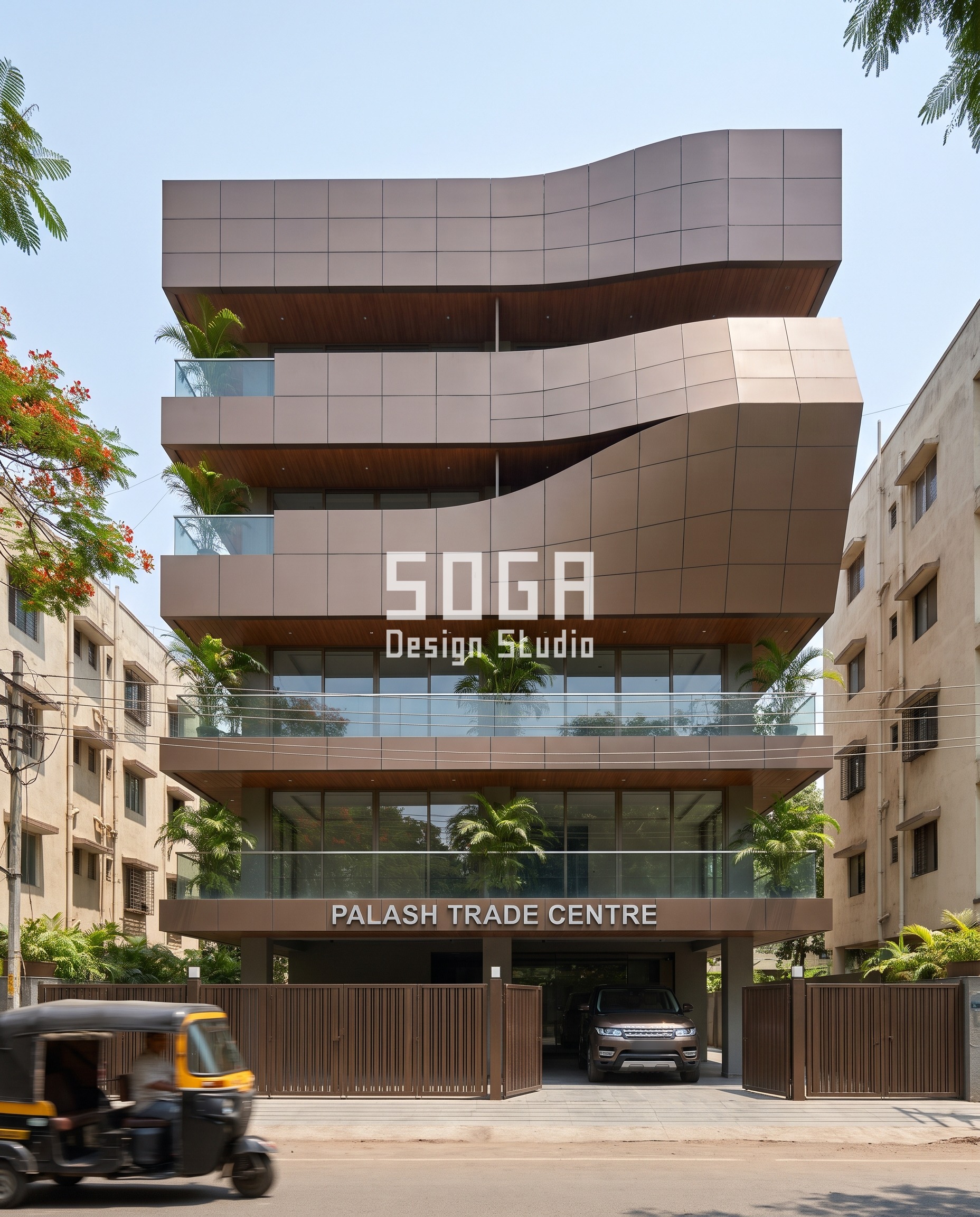
The three main digital cutting methods — CNC routing, laser cutting and abrasive waterjet cutting — are not interchangeable. A shop picks the method the material and the finish actually need, not whichever machine happens to be free that week.
| Material | CNC Routing | Laser Cutting | Waterjet Cutting | Achievable Tolerance (mm, indicative) |
|---|---|---|---|---|
| GFRC (cured panel) | Used only on the mould or pattern, not the cured panel itself | Not applicable — GFRC is not a laser-cuttable material | Edge trimming only; rarely the primary cutting step | ±2–3 mm on the mould, before mix design and cure variance are added |
| Composite metal panel (ACP sheet) | The default route — grooves the back face so the sheet folds along a clean crease | Used for perforated or fine-pattern faces; heat can discolour a painted finish if settings aren’t controlled | Workable but rarely chosen for simple folds — slower, and wastes material | ±0.3–0.5 mm (laser); ±0.5–0.8 mm (routing) |
| Stainless or mild steel sheet | Rare — routing bits wear quickly on steel; reserved for thick plate | The standard method for perforated and fine-pattern steel screens | Used for thick plate (6 mm and above) or where heat distortion must be avoided | ±0.1–0.2 mm (laser, thin sheet); ±0.3–0.5 mm (waterjet, thick plate) |
| Natural stone / stone veneer | Used for edge profiling and chamfers, not through-cutting | Not used — stone does not respond to a laser beam | The standard method — abrasive waterjet cuts intricate perforated patterns without heat-cracking the stone | ±1–2 mm, wider than metal because stone chips slightly at the kerf edge |
| Timber / timber-look composite | The default route — suits wood and composite boards well, and can carve shallow relief | Rarely used — the charred cut edge needs sanding back, adding a step | Not typically used | ±0.5–1 mm, depending on moisture content and grain |
Indicative only — basis: SOGA’s 2026 vendor quotations for mid-volume facade panel runs across Delhi-NCR and Bangalore fabrication clusters, material cost excluded. Actual tolerance also depends on machine condition, sheet thickness and operator setup. Glass fibre reinforced concrete panels are formed in a mould rather than cut from stock, which is why their tolerance is governed by the mould and the cure, not by a cutting machine.
Start Your Facade Fabrication Package
If a parametric facade is at the model stage and needs a structural check, panel rationalisation and a fabrication-ready release, SOGA Design Studio runs this exact seven-stage process for Indian projects. Start a conversation about your facade.

What Happens On The Factory Floor After The CNC File Is Released?
Once the cut file is released, the shop floor runs its own sequence, and most of it is ordinary sheet-metal and stone work rather than anything specific to parametric design.
- Cutting. Flat blanks are cut to the nested pattern by the chosen method and marked with the panel’s shop-drawing number before they leave the cutting table.
- Forming. Panels are folded on a press brake, pressed in a die or roll-formed to the modelled profile; depth and springback are measured on the first article from each panel family before the rest of the batch runs.
- Finishing. Coating, anodising or a patina is applied in a separate finishing bay; finish thickness and adhesion are checked on sample panels per batch.
- Dimensional inspection. Each finished panel is checked against its shop drawing on a flat table before it is packed, not after it reaches site.
The 3D block facade manufacturing process is a useful worked example of exactly this sequence for a deep-folded panel family, where depth tolerance and springback are the hardest things to hold across a batch.
How Does A Facade Panel Travel From Workshop To Site Without Damage?
A panel that passed inspection in the shop can still arrive at site damaged or out of sequence, so packing and transport get their own checks.
- Panels are crated with corner and edge protection matched to the finish — a polished or coated face needs more padding than a mill-finish one.
- Delivery batches are sequenced to match the erection plan, so the crew installing a given elevation bay is not waiting on a panel still in transit three cities away.
- Every crate carries the same panel number used on the shop drawing, so a site team can match delivered panels to the installation sequence without re-measuring each one.
- Panels are inspected again on arrival, before unloading is signed off, because transport damage is a different claim from a fabrication defect and needs to be caught at the gate.
What Tolerance And QC Checks Happen During Site Installation?
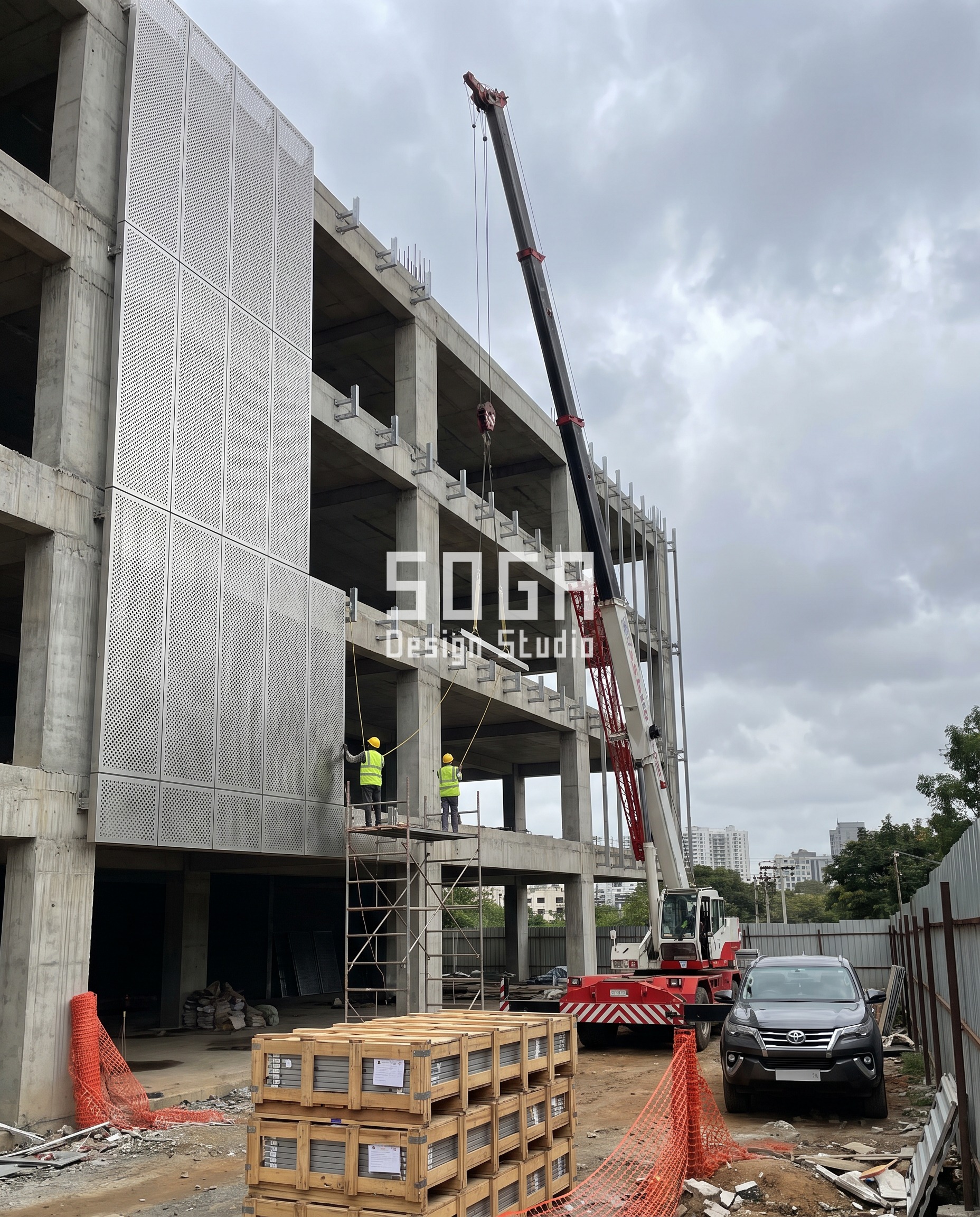
Site installation has its own checks, independent of whatever tolerance the panel held in the shop. The site supervision checklist and the bracket-and-anchor survey both feed this stage directly.
- Bracket survey. Bracket positions are surveyed against the as-built RCC frame, not the drawing, because slab edges rarely land exactly where the structural drawing says they will.
- Laser-level alignment. Panels are set to line and level with a laser level, not by eye, especially across a long frontal run where a small per-panel drift compounds visibly by the far end.
- Joint-width check. Joints are gapped to the design width for thermal movement, per the joint-width and thermal movement rules for the material and the local temperature swing.
- Mockup comparison. The installed bay is checked against the approved mockup panel, not against the render, because the mockup is the only reference that was ever meant to be matched exactly.
- Punch list closure. A final walk closes out any panel needing a shim, a touch-up or a re-seal before handover.
What Can Go Wrong Between The Model And The Installed Panel?
A facade rationalised to a dozen panel families for shop efficiency will always read slightly more repetitive on site than the single continuous sweep in the render promised — the eye catches the seam every 1.2 to 1.8 metres where panels butt, and a render never shows that because it rarely models panel joints at all. The second, less glamorous gap is dimensional: a panel cut to a 0.2mm waterjet tolerance can still arrive 4–5mm out of position on site if the RCC slab edge it is fixed to was not surveyed to the same tolerance. A facade’s finished accuracy is only ever as good as the building it is bolted to, and closing that gap — with shimmed brackets, not a redesigned panel — is the fabricator’s most common and least photographed line item.
Frequently Asked Questions
What is the first step in turning a parametric facade design into a fabrication-ready file?
The computational design model is checked by a structural engineer for panel self-weight and wind load, then broken into manufacturable panel families sized to available stock sheet and transport limits. Only after that panel rationalisation is a CNC cut file released to the shop floor.
How long does it take to go from a signed-off facade model to the first fabricated panel in India?
Indicative basis: SOGA’s 2026 project schedules for a mid-sized Indian facade package. Structural checks and panelisation typically run 2–4 weeks, fabrication drawings and CNC output a further 3–5 working days, and first-article cutting and forming another 1–2 weeks before the first approved panel leaves the shop.
Which cutting method gives the tightest tolerance for a metal facade screen?
Laser cutting on thin stainless or mild steel sheet typically holds the tightest tolerance, around ±0.1–0.2mm, which is why it is the standard method for fine perforated steel screens. Waterjet cutting is reserved for thicker plate or heat-sensitive materials where laser distortion is a risk.
Can a facade panel be fixed to the building without a sample panel or mockup first?
Not on a properly run project. A full-scale mockup or sample bay is built and approved before batch fabrication begins, because a swatch or a single panel cannot show how the finish, joint lines and lighting read across a whole elevation.
Who checks a facade design model for structural safety before fabrication begins?
A structural engineer, working from the facade designer’s panel geometry and bracket layout, reviews self-weight, wind suction on projecting elements and the load path back into the RCC slab edge, and signs off the maximum permissible panel span before panelisation is finalised.
Does a CNC-cut facade panel always match the design render exactly?
Not quite. Rationalising a continuous parametric sweep into a manageable number of panel families introduces visible joints a render never shows, and the panel’s final position on site depends on how accurately the RCC structure it is fixed to was built, not only on how accurately it was cut.
Related Reading
- Parametric Facade Design in India: Systems, Materials & Cost per Sq Ft
- Computational Design for Facades in India: From Algorithm to Fabrication Drawing
- Designed in India, Engineered in India: How Parametric Facade Systems Became Manufacturable
- From Concept to Construction: How Parametric Facades Are Designed and Built in India
- Facade Fixing Bracket Anchor Into RCC Slab: Survey First
- Facade Panel Joint Width and Thermal Movement in India
- The Elevation Mockup: Build One Bay Before The Whole Face
- Elevation Site Checklist: What To Inspect At Each Stage
- Facade Shop Drawing Review for Architects: A Checklist
- How SOGA 3D Block Facade Panels Are Manufactured: Folding, Depth Tolerance and Rigidity
Get A Fabrication-Ready Facade Package
SOGA Design Studio takes a parametric facade from computational design model through structural sign-off, panelisation, CNC-ready drawings and site installation QC as one tracked package for Indian projects. Talk to the studio about your facade’s fabrication plan.