A coin facade is easy to draw and difficult to hold still. Set a field of circular discs in front of a building, vary their size and angle, and the elevation appears to open and close as a person walks past. Working out how each disc is carried, what stops it moving in wind, and how one comes off when it is damaged takes considerably longer.
The system is normally introduced through its visual effect, which is the least useful way to understand it. A coin facade is a screening layer made of discrete objects, and nearly every problem it presents follows from that word: each disc has its own restraint condition, its own local wind load, its own edge to protect and its own path back to structure.
The SOGA Coin Facade is a coin facade system developed by SOGA Design Studio for Indian fabrication. What follows is written from that development work rather than from a survey of the category: the prototypes, the fabrication trials and the installation testing that settled how a disc is restrained, and how one comes off when it is damaged.
A coin facade is a parametric cladding system built from circular metal discs mounted on a carrier frame or vertical spines. Each disc can vary in diameter, spacing and rotation angle, so the facade shifts between open and closed as the viewer moves. Discs are individually replaceable and typically allow airflow, daylight and filtered views.
What a coin facade is — and what it is not
A coin facade is a secondary screening layer: a field of circular formed discs on a carrier structure, set in front of a wall, a glazed line, a deck edge or an open service zone. It modifies what crosses the plane it occupies — daylight, view, air, some proportion of driven rain.
It is not a weather line. It is not air-sealed, it does not resist water penetration, and it has no thermal performance of its own. In front of glazing, the glazing remains the weather line and keeps responsibility for thermal and acoustic performance.
It is also not a perforated panel. A perforated sheet is one continuous element with material removed, and it spans between fixings. A coin field is the inverse: nothing spans, and every disc must be separately located, restrained and given a load path. The connection count is an order of magnitude higher, which is where the cost sits.
Nor is it kinetic by default. In most built work the discs are fixed and the apparent movement comes from viewing angle rather than motion. Configurations permitting real rotation bring bearing wear, noise and gust behaviour that has to be tested.
Anatomy of a coin panel
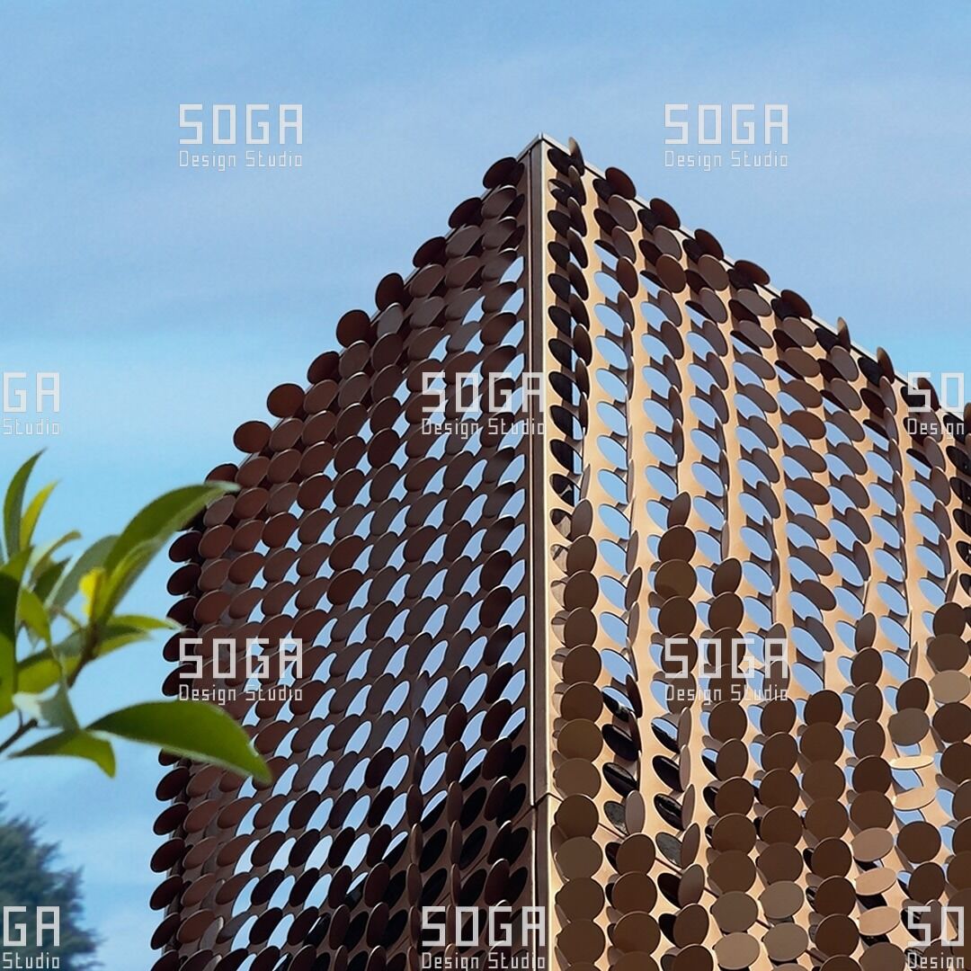
A coin panel is four things in a line: the disc, the element carrying it, the carrier grid positioning those elements, and the connection back to primary structure. Each layer does one job, and the discipline of the system is keeping them separate. Merge two to save money — weld the disc to its carrier — and the prospect of replacing one disc goes with them.
Disc geometry, edge condition and depth
The disc is rarely a flat cut circle, and understanding why explains most of what it costs. A flat circle has three weaknesses. It has almost no out-of-plane stiffness, so it flutters at low pressures; its edge reads as a section through a sheet rather than the edge of an object; and a bare cut edge is where coating is thinnest, which makes it where corrosion starts.
Dishing and rim forming answer all three. Shallow double curvature is what makes thin material stiff, and it removes most of the flutter risk without added weight. Rolling the rim turns the edge back on itself, so the coating sits on a radius rather than a sharp arris and the disc reads as a solid object.
Diameter and thickness are coupled. Increasing diameter at constant thickness makes the disc more flexible, more prone to flutter and heavier at its fixing. The recurring failure is a late diameter change made for visual reasons, after which the behaviour of every disc has changed and nobody rechecks it.
The spine, pivot or rod that carries the disc
The carrying element determines wind behaviour, replacement method and substructure demand.
A through-rod or spine runs vertically behind or through a column of discs, each disc sitting against a spacer or collar that sets its height and, when keyed, its rotation. It is the most economical arrangement for tall regular fields, because connections back to structure stay few. The rod becomes a structural element with its own deflection.
A pivot or stub axle fixes each disc individually to a carrier member, rigidly at a set angle or on a bearing running between defined stops. It gives control disc by disc, which is what allows rotation to be graded across an elevation, and it multiplies component count and site operations.
A frame-mounted cassette assembles a group of discs onto a frame in the workshop and delivers the result as a unit. Assembly labour moves off the scaffold, and single-disc replacement is lost unless discs stay demountable within the frame.
One principle sits under all three. A disc held at one point can rotate and vibrate about it; a disc held at two points can do neither. Every fixed configuration that works has found its second restraint somewhere — a keyed collar, a locating pin, a machined flat. Where restraint comes only from friction at one fastener, thermal cycling relaxes the joint, discs drift out of rotation, and the facade chatters. That was the constraint that shaped SOGA’s approach to the carrier, and it is why the collar in the SOGA Coin Facade sets rotation with a key rather than with clamping force.
Single-disc replacement is claimed more often than it is detailed. If a disc can only be released by withdrawing the whole spine, the facade does not have it.
Coin panel component schedule (indicative)
Every item arriving on site as a separate part belongs here. A missing line means someone has assumed it will be resolved later.
- Disc — formed, edge-treated, finished, counted by diameter and dish type.
- Carrier spine, rod or stub axle — stated section, length and end condition.
- Spacer or collar — sets pitch, and when keyed, sets rotation.
- Locating feature — keyway, flat, pin or boss preventing rotation under load.
- Fastener set — material, coating, tightening requirement and locking method.
- Isolation washer or sleeve — at every interface between dissimilar metals.
- Head and base bracket — adjustment range stated separately for each axis.
- Carrier member — the grid or rail receiving the brackets.
- Structural fixing — cast-in channel, anchor or plate, to a stated design load.
- Movement provision — slotted holes or sliding sleeves on continuous runs.
- Identification marking — a position code on each disc in a graded field.
Pattern parameters: pitch, density, rotation, offset
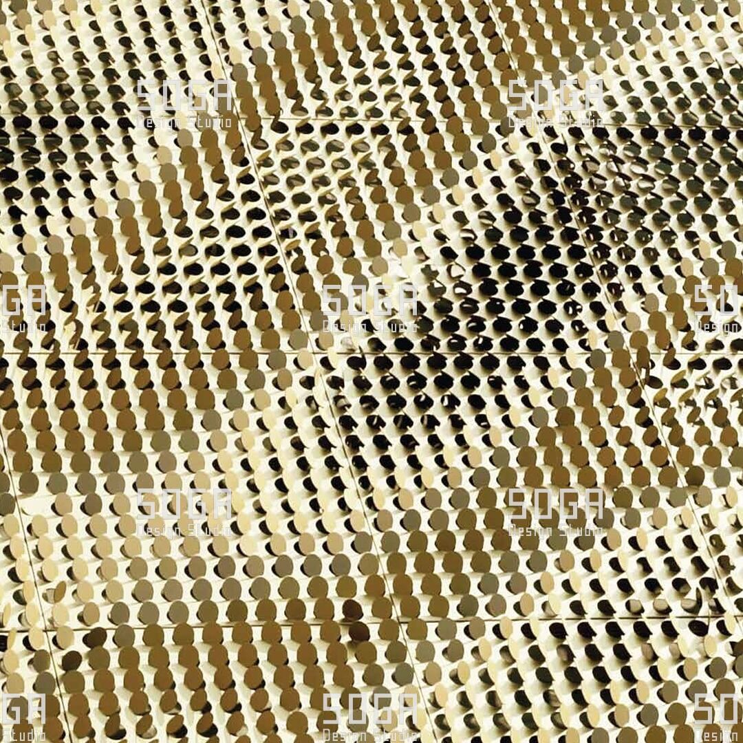
Four numbers generate the pattern, and all four can vary across an elevation without changing the parts being manufactured. Variation is carried by position and rotation rather than shape, which is the economic basis of the system.
Pitch is centre-to-centre spacing, stated separately in each direction, and the primary control on openness. It is tuned against openness and wind targets, and it is usually the first thing that moves when either is tested.
Density is the relationship between diameter and pitch. Two elevations at the same pitch with different diameters have different openness, wind loads and shadow depth, so a pitch quoted without a diameter says nothing.
Rotation is the angle of each disc relative to the facade plane. At zero rotation the disc presents full area and blocks most light; as rotation increases, projected area falls and the surface reads as tilted planes catching light at different intensities.
Offset is the stagger between adjacent columns. An orthogonal grid leaves clear sight paths straight through, while a staggered offset interrupts them and raises apparent density without adding a disc.
Two constraints discipline the pattern from outside. Disc positions must reconcile with structural bays, floor levels, movement joints and openings. And discs are not cut: a field terminates by leaving discs out, or against a border, because a sliced disc reads as an accident.
The parameters interact, which is why the pattern is resolved in computational modelling rather than drawn as an elevation. The useful output is not the image. It is the schedule: how many disc types exist, how many of each, and where each goes. SOGA issues that schedule as the primary fabrication deliverable, with the elevation carried alongside it as a reference rather than the other way round.
How parameters translate into openness and shadow
Openness should be a target set at the start, not a figure discovered at the end. Two openness numbers matter and they are not interchangeable.
Normal openness is free area measured perpendicular to the facade. It governs air movement through the screen and it is the number that counts where ventilation is a regulatory requirement.
Oblique openness is free area seen along a sight line at an angle, and it falls away quickly as that angle increases. A screen substantially open on paper can read as almost solid along the length of an elevation. That asymmetry is often the point — occupants keep their view while the street sees mostly disc — and a problem when the brief wanted the reverse.
Shadow follows from rotation and dish depth. Flat discs at zero rotation read as a graphic pattern that barely changes through the day, while graded rotation casts shadows of varying length and direction. The common failure is a rotation range set too narrow: the field is graded across so few degrees that nobody perceives a gradient, at the fabrication cost of one that works.
| Configuration | Disc rotation | Openness band | Wind sensitivity | Maintenance access | Typical application |
|---|---|---|---|---|---|
| Fixed flat | Zero; discs parallel to the facade plane | Lowest for a given pitch | Highest; full projected area presented | Simple; disc releases from its collar | Graphic elevations, signage walls, low-rise screens |
| Fixed angled | Constant set angle across the field | Moderate, tuned by angle | Moderate; reduced projected area | Simple; keyed collar released | Shading screens, east and west elevations |
| Free-pivot limited | Free within defined mechanical stops | Varies through the day | Governed by stop and bearing design; noise risk | Higher; bearings are a wearing part | Feature elevations where movement is the stated intent |
| Graded density | Varied disc by disc across the field | Widest range achievable on one elevation | Assessed zone by zone, never as an average | Simple, provided disc types are identifiable | Long elevations, open-to-closed transitions |
| Double-layer | Two planes at differing rotation and offset | Lowest oblique openness of any configuration | Highest; two planes plus shielding effects | Difficult; the outer layer obstructs the inner | Privacy screens, plant rooms, car park facades |
Double-layer fields add one behaviour. Two overlaid patterns of slightly different pitch generate moiré interference, which shifts by a large amount for a few millimetres of deviation between the layers — powerful when it is intended, a defect the installer is blamed for when it is not.
Structural logic and load path
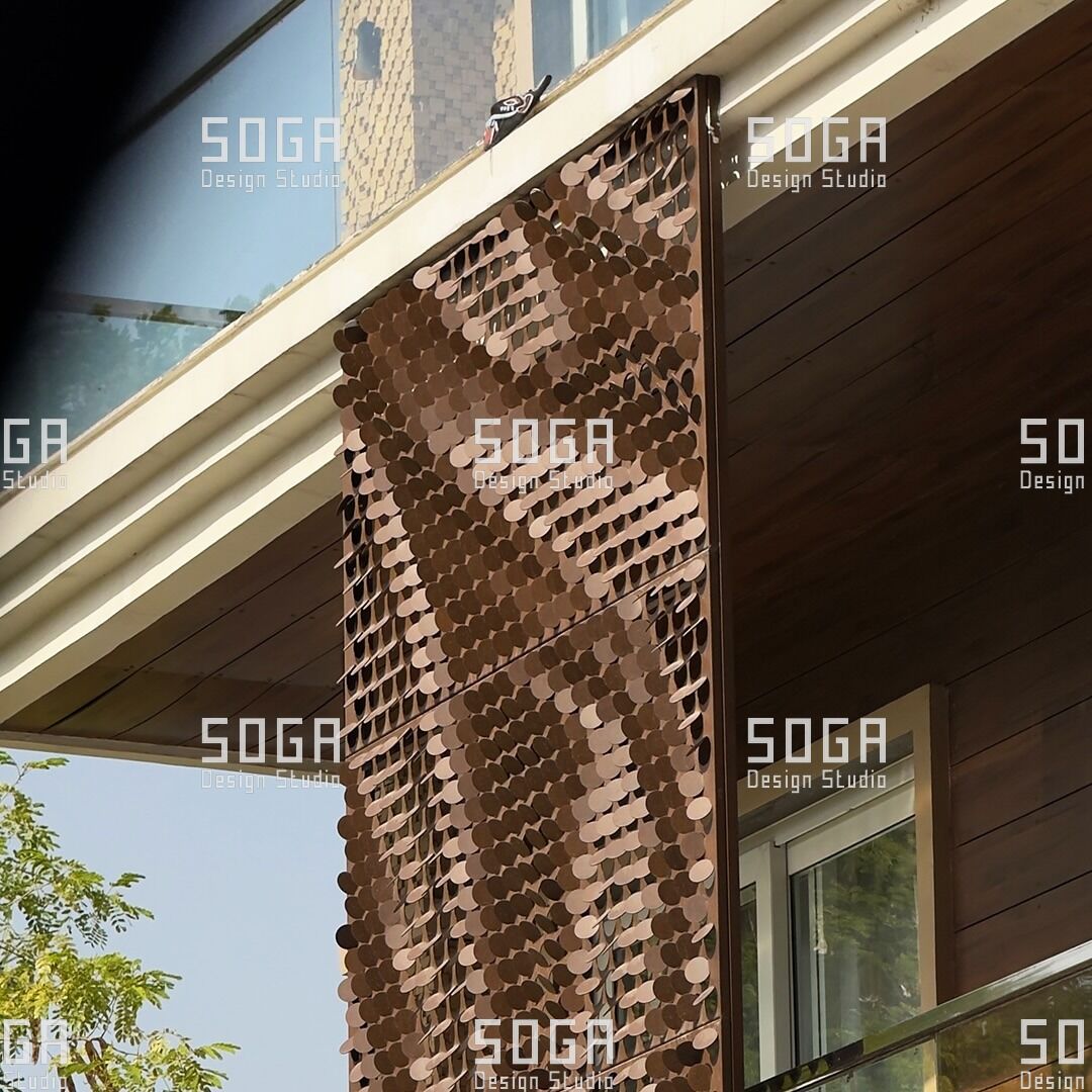
The load path runs from disc, to spine or stub axle, to bracket, to carrier member, to structural fixing, to primary structure. At each of those six interfaces the load changes direction and some of the available tolerance is consumed. An engineered screen documents that chain with a load and a capacity at every step.
Dead load, wind load and fixing back to structure
Dead load is modest and rarely governs. What matters is load at each fixing and the moment with it, because a disc field standing off the wall applies its weight at an eccentricity. Stand-off distance belongs in the bracket calculation from the start.
Wind load is the design case. Porous screens attract lower net pressure than solid cladding, but small elements attract high local coefficients near corners, parapets and free ends, so edge-zone fixing spacing is not field spacing. The screen also does not relieve the wall behind it unless shielding has been demonstrated. Design pressure comes from the project’s own wind assessment for that location and exposure, never from a figure carried over from a previous job.
The hardest case is neither. It is dynamic excitation: a circular element sheds vortices, and at particular wind speeds that shedding excites an assembly which amplifies it. This is the mechanism behind chatter, the low irregular tapping a poorly restrained disc field produces on a windy afternoon and which is impossible to ignore from a room behind the screen. It is addressed by stiffening the assembly, adding the second restraint point, damping at the collar and breaking up regularity. Regularity makes the pattern legible; it also lets an elevation resonate together.
Thermal movement is the omission that shows up on long runs. A continuous carrier changes length measurably across the annual range on an Indian or Gulf site, and fixed rigidly at both ends it will bow or tear at its fixings. Fixed and sliding points belong on the drawings.
Bimetallic corrosion is a specification item, not a site judgement. Wherever the panel material meets a fastener or bracket of a different metal in the presence of moisture, isolation is required. Its absence is invisible for two years, then appears as staining below every fixing.
A disc is a discrete object suspended above a public area, so positive mechanical location is the standard rather than friction alone.
Fabrication in outline
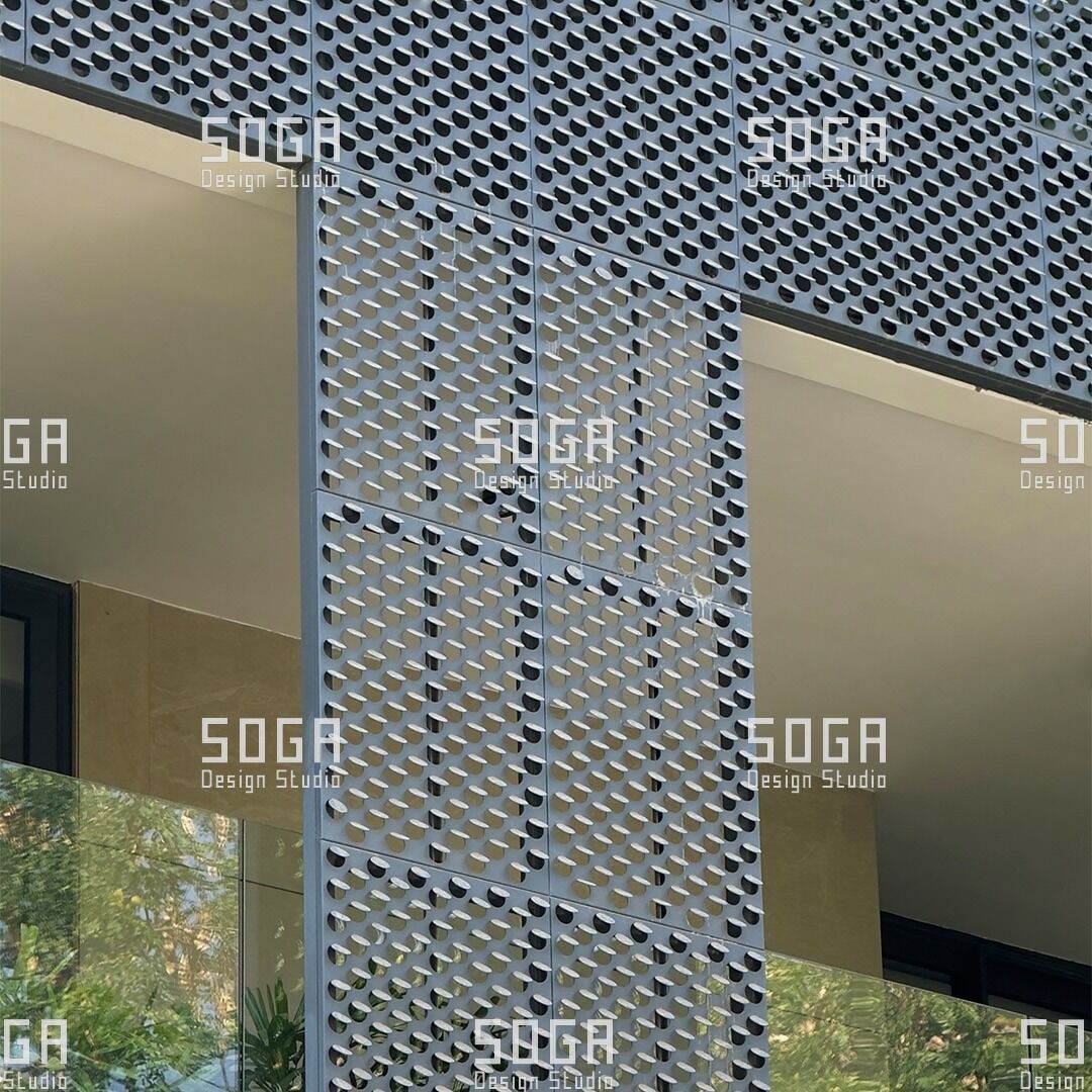
Coin facade fabrication uses processes ordinary metal shops already run: cutting, forming, deburring, finishing, assembly. What it needs is control between those operations, and inspection that catches drift before several hundred discs have been made wrong.
Blanking, forming, deburring, finishing
Blanking produces the circular blank, and the engineering issue is nesting. Circles nest poorly, and the material between them is waste carried in the price whether or not it is itemised. Nesting mixed diameters recovers a share of it.
Forming creates the dish and the rim. Springback is the recurring problem: formed material relaxes after leaving the tool by an amount that varies with batch, thickness and temperature, so dish depth drifts through a run. It is controlled by over-forming a calibrated amount and inspecting the first article. The allowance is not a table figure. SOGA establishes it with the fabricator during trials and re-checks it whenever thickness, tooling or material batch changes.
Deburring is the operation most likely to be compressed when a programme slips, and the one that decides how the facade looks at ten years. A cut edge carries burrs and a hardened zone from thermal cutting. Both go before finishing: coating over a burr is a thin film over a sharp point.
Finishing is applied after forming, never before: forming a pre-finished blank crazes the coating at the rim and the dish transition, where the eye goes. The specification should describe surface preparation, pretreatment, coating system, film thickness, cure schedule and adhesion testing, not only a colour.
Marking is routinely left off drawings. Discs of different dish depth look alike in a crate, so a graded field needs a position code on every disc and packing that follows the installation sequence.
Installation and tolerance
Installation decides the economics of a coin facade. The disc is inexpensive; the disc delivered, lifted, positioned, aligned and accepted is not, and installed labour usually exceeds component cost. A detail that removes a site operation is worth more than an equivalent saving in material.
Setting out, sequencing, adjustment allowance
Setting out begins from a survey of the structure as built, not as drawn. A frame deviates in plan, in level and in plumb; those deviations are normal and the facade absorbs them. The carrier is set to a corrected datum from that survey, because setting out bay by bay delivers the accumulated error to the last bay.
Sequencing follows. Carriers are installed across the full elevation and checked as a set before disc installation starts, because a carrier line out by a small amount is adjustable while empty and expensive to correct once loaded. Whatever reaches the screen during installation is what will reach it for cleaning.
Adjustment allowance has to be designed, stated and drawn rather than improvised. The bracket needs movement in three axes, with the available range documented in each and compared against the tolerance the frame is actually being built to. If the two do not overlap with margin the facade will not fit, and that is established on paper rather than on a scaffold. SOGA’s installation mock-ups are where the stated range gets tested against the way a crew actually works, because a range that exists on a drawing and a range an installer can reach are not always the same thing.
One tolerance question favours disc fields. The eye reads the alignment of disc centres and the consistency of the gaps; deviation perpendicular to the facade plane is barely perceptible between separated circular objects, where a flush panel would advertise it at every joint.
Performance: daylight, privacy, acoustics, maintenance
A coin facade delivers measurable performance in two areas, negligible performance in one, and its maintenance behaviour is assessed too late more often than not.
Daylight and solar control. The screen shades by interception, blocking part of the direct radiation while leaving diffuse light and outward view largely intact. Effectiveness depends on orientation. On east and west elevations the sun is low and sweeps a wide azimuth range, so a graded rotation field works well where no fixed angle would; high sun on a south elevation is handled more efficiently by horizontal shading. Shading has to be modelled against orientation and latitude, not inferred from an openness figure.
Privacy and view. The asymmetry between normal and oblique openness does the work in daylight. It reverses after dark: with the interior lit and the exterior dark, the screen gives very little privacy. That is worth stating in writing at design stage.
Acoustics. A coin facade is not an acoustic barrier. It is porous by definition, so transmission loss is negligible. It does scatter, diffusing reflected sound rather than returning it cleanly, and it can generate noise through chatter and wind across edges.
Maintenance and cleaning. The advantage is granularity: a damaged disc comes off its collar and a replacement goes on without disturbing neighbours, provided the fixing permits it and the replacement can be matched — which is what batch traceability and a retained sample set are for. Cleaning is harder. A disc field presents far more surface area than the elevation it covers, much of it facing upward and collecting dust, in most Indian and Gulf urban contexts the dominant maintenance driver. Rotation direction, not only angle, is a maintenance decision.
Where coin facades work best — and where they do not
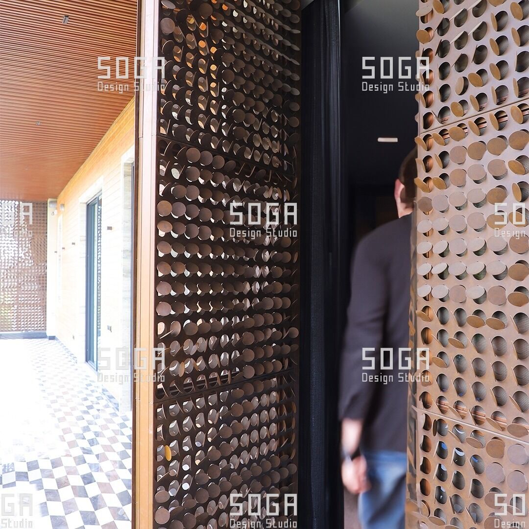
The system suits situations where something needs screening without being enclosed, and where the surface behind tolerates weather passing through.
Naturally ventilated car park decks are the clearest case: free area is required by regulation and visual treatment by planning consent, and a disc field delivers both against a measurable openness figure. Plant rooms, service zones and refuse areas are the same problem at smaller scale. Disc screens also work over balcony edges, staircase cores and service shafts, and on retail elevations the system does identity work without signage.
The disqualifying conditions are equally specific. Where the screen is expected to act as a weather line, it cannot. Where the space behind is acoustically sensitive and the elevation exposed, chatter risk should be resolved before selection, not after the first windy season. Where no realistic cleaning access exists, appearance will degrade and the system will be blamed for an access decision. On coastal and polluted sites the finish and fastener specifications carry more weight than the pattern.
| Failure mode | Mechanism | Where it shows up | Design response |
|---|---|---|---|
| Chatter and wind noise | Single-point restraint permits oscillation; a regular field responds in phase | Rooms behind the screen, first windy season | Second restraint point, damping, deliberate irregularity |
| Bimetallic corrosion | Dissimilar metals in contact with moisture present | Staining from fixing points, after year two | Isolation washer or sleeve at every dissimilar interface |
| Edge corrosion | Coating thins over burrs and cut edges | Disc rim, visible at close range | Full deburr before finishing; finish after forming |
| Visible misalignment | Set out bay by bay rather than from a corrected datum | The last bays of a long elevation | As-built survey; carriers checked as a set before discs are hung |
| Transposed disc types | Graded field installed without position marking | Gradient subtly wrong across the elevation | Position codes on every disc; packing matched to install sequence |
| Dust accumulation | Upward-facing dish surfaces act as shallow trays | Whole elevation, by year two or three | Rotation direction chosen against dust; access fixed at design stage |
Specification checklist for architects
If you are assessing a coin facade proposal, these questions separate a system from an elevation drawing. Ask them before the pattern is fixed.
- How many unique disc types are in this facade? Ask separately for diameters, dish depths and rotation settings. If nobody can give a number, the design has not been rationalised.
- What is the restraint condition at every disc? Look for positive mechanical location rather than friction from one fastener.
- What design wind pressure has been used, and where did it come from? It should be your own project’s assessment, with edge and corner zones evaluated separately.
- Has the dynamic case been considered, not only the static one? Ask what prevents the field oscillating in phase.
- What adjustment does the bracket allow, in which axes, over what range? Compare it against the tolerance the frame is being built to.
- Does the screen relieve wind load on the wall behind it? If that has not been demonstrated, assume it does not.
- When is the finish applied relative to forming? After forming. If the answer is before, expect crazing at the rim.
- How does one damaged disc come off, and in which direction? If neighbours move first, your lifetime maintenance cost is not what you were told.
- What is the cleaning access strategy, and who has signed it off? This is answered at design stage or never.
- Has a full-height mock-up been built, and what installation rate did it produce? A measured rate is the difference between a priced facade and a guessed one.
A proposal answering all ten is a system. One answering fewer than six is a concept, whatever the elevation drawing shows.
How SOGA developed this system
The problem that started the work was restraint. A disc hung on a single fastener is free to rotate about it and free to vibrate about it, and Indian conditions do not hold that joint for long: a cast frame deviates, a fastener is tightened by hand on a scaffold, and the annual temperature range relaxes anything relying on friction. Fields built that way drift out of rotation and chatter through the first windy season. SOGA developed the SOGA Coin Facade to produce a disc field that stays where it is put and can still be taken apart one disc at a time.
The work ran as a loop. Prototypes established whether a dished, rim-rolled disc could be formed consistently in thin sheet. Structural studies covered the spine, the bracket and the eccentricity of a screen standing off a wall. Fabrication experiments moved the parts onto a production floor at real batch sizes, which is where the drawings changed most. Installation testing used a mock-up built the way a site builds; manufacturing optimisation followed once the part family was fixed.
Two things changed between the first prototype and the production system. The first was the restraint. The prototype relied on friction at one fastener; the production disc is located positively, by a keyed collar and a locating feature that hold rotation regardless of how tight the fastener ends up. The second was the release direction. The early carrier could only be unloaded by withdrawing the spine, so one damaged disc took its column of neighbours with it. The production carrier releases a disc at its collar, outward, leaving the spine and the discs above and below undisturbed.
Development sat inside the six-months-to-a-year range the studio’s systems generally take.
It is manufacturable in India because every operation it needs — blanking, dishing, rim rolling, deburring, finishing — is one Indian metal shops already run in long batches.
SOGA Design Studio is a parametric and computational architecture practice based in Gurugram, working across India, Dubai and Singapore, specialising in facade systems engineered for local fabrication.
Frequently asked questions
Is a coin facade a kinetic facade?
Not necessarily, and usually not. Discs may be fixed at a set rotation or allowed limited free movement between stops, and the shimmer most people associate with the system comes from viewing angle rather than motion. Genuine free movement is a separate engineering decision with its own wear and noise consequences.
Can a coin facade be used on a residential building?
Yes, and it is one of the more common applications, typically as a screen over balcony edges, staircase cores and service zones. Density is tuned to balance privacy from the street against ventilation and the resident’s own view out. The point to state at design stage is that privacy reverses after dark.
How are damaged discs replaced?
An individual disc is removed from its carrier and replaced without dismantling neighbouring panels, which keeps maintenance local rather than area-wide. This holds only if the fixing was detailed for it, so the release direction should be checked on the drawings. Retained samples from the original batch allow a replacement to match in tone.
What spacing is typical between discs?
Spacing is a design parameter rather than a fixed value, and it means little without the disc diameter alongside it. It is tuned against openness and wind targets on each project rather than taken from a standard figure, and it should always be quoted alongside the disc diameter it belongs to.
What the system is actually good at
Strip away the visual language and a coin facade does one thing precisely. It converts a small family of repeated parts into a continuously varying surface, using position and rotation instead of shape. The workshop makes a few things many times, the only condition under which metal fabrication is economical, and the elevation still reads as varied.
The engineering that makes this work is not exotic. Restraint designed for two points rather than one. A load path documented interface by interface. A finishing specification describing a process rather than a colour. A replacement procedure drawn rather than assumed. All of it settled before the pattern is fixed, because a pattern developed without it gets redesigned.
The system was designed in India and engineered in India, against Indian fabrication and Indian sites. It travels for the same reason it works here: long batches of ordinary operations in the workshop, and nothing asked of the scaffold that a scaffold cannot reliably supply.
The system drawings behind this guide are available for review if you are testing a coin facade against a specific elevation.