We draw cross ventilation arrows through party walls that are never going to be opened. The drawing gets signed, the client is served, and nobody in the room says the obvious thing out loud: on a narrow plot with neighbours hard against both sides, there is no cross ventilation to design. There is one face.
Single-sided ventilation is what a narrow Indian plot with party walls on both sides actually has: one open face, where air must enter and leave through the same facade. It is not cross ventilation, and no window size converts it into cross ventilation. On such a plot the front elevation is not decoration sitting on top of the ventilation system. It is the ventilation system.
A narrow plot with party walls both sides has no cross ventilation: air enters and leaves through the one open face. CIBSE AM10 caps the room at 2.0 times ceiling height, or 2.5 times with paired high and low openings — 6.0 m and 7.5 m at a 3.0 m ceiling.
The remainder is direction. Openable area is a quantity; it says how much air can pass. It says nothing at all about where that air goes once it crosses the wall plane, and on a single open face that is the only question that matters. Air on one face is not pushed through the room by a pressure difference across the building, because there is no across. It arrives as a stream, and a stream has a heading. Get the heading wrong and a 15 per cent openable wall delivers a jet along the ceiling, out again through the top of the same window, and 1.2 m into a 6 m room. The code has no clause for this. Nobody prices it. And the screen in front of the window — the thing every one of these houses already has, for privacy or for sun — is the only instrument on the building that can set that heading. It is almost always drawn as a pattern.
Why the Party Wall Is Arithmetic, Not Laziness
The party wall is not a mistake, it is arithmetic. On a standard 25 ft frontage — 7.62 m — a 1.2 m side setback takes 15.7 per cent of your built width off every single floor. On a 15 m deep plot that is 18.0 sq m, 194 sq ft per floor, 775 sq ft across a G+3. On a narrow plot that is a bedroom on every level, surrendered. Worse, what you buy for it is usually not a second face at all: a 1.2 m slot between two blank walls is a light well with almost no pressure difference across it. The owner who builds to the party line is reading the site correctly. NBC 2016 Part 8 asks for openable area of at least 10 per cent of floor area in habitable rooms, and that is easy to hit on one face — so the drawing is legal, the client is served, and the arithmetic is sound. We have drawn that plan ourselves, with the little curved arrows on it, and signed it.
The Roshandan Already Solved the One-Wall Room
The roshandan (रोशनदान, “light-giver”) is a small fixed ventilator set high in the wall, within about 300 mm of the ceiling and usually 300 to 450 mm tall, sitting directly above the main window or door and filled with louvres, a cast grille or coloured glass. It is almost never openable. It is in the wall of most pre-1960 houses across north India, and in the row houses of old Delhi, Lucknow and Kanpur it sits on plots built wall to wall with exactly one open face. Same plot problem, a century earlier, and nobody treated it as decoration.
The height separation is the engineering. A room with one window ventilates by turbulent exchange across a single aperture: air enters through part of the opening and leaves through another part of the same opening, and the two flows spend most of their energy fighting each other in the same hole. Add a second opening near the ceiling and the room stops arguing with itself. Warm used air leaves high, cooler air enters low, and the driving pressure is no longer the weather but the height between the two openings multiplied by the temperature difference across them. This is why CIBSE AM10 rates a single-opening room at about 2.0 times its floor-to-ceiling height and a room with a paired high and low opening at about 2.5 times — at a 3.0 m ceiling, 6.0 m against 7.5 m of usable depth. The roshandan bought a metre and a half of room with a 400 mm hole, and it bought it without a second wall.
The roshandan is not what the five concepts below are. It is what they assume. Every system on this page aims air through a front face that is doing all of the work, and the extra metre and a half is only available if something at high level lets the used air out. Aim the inlet with the facade; keep the outlet, or accept the shallower number.
The Rule: Aim the Only Opening You Have
Aim the only opening you have. That is the whole method, and it is a sentence about direction, not about size. On a plot with one open face you are not choosing how much air to admit — the code already put a floor under that, and it is easy to clear. You are choosing where the air goes after it crosses the wall plane, and the only instrument on the building that can make that choice is the screen in front of the window: its depth, its tilt, its reach, its pitch. Those are third-dimension quantities. They do not appear in an elevation drawing and they do not move the free area by a single percentage point. So the five concepts below are built as a control. In every one of them the opening size, the pitch and the spacing are held exactly constant from the top floor to the first, and exactly one third-dimension quantity is moved down the face. Nizamabad moves blade plan-depth 90 to 340 mm. Sangli moves plate tilt 0 to 26 degrees. Kollam moves prow run-out 600 to 1,650 mm. Muzaffarpur moves vane angle 0 to 44 degrees. Shivamogga moves crossing depth 60 to 340 mm. If a room behaves differently floor to floor, there is only one thing it can be.
How Deep Can a Room Be With Windows on Only One Wall?
About 6.0 m with a single opening and about 7.5 m with a paired high and low opening, at a 3.0 m floor-to-ceiling height. CIBSE AM10 limits single-sided natural ventilation to a room depth of roughly 2.0 times the floor-to-ceiling height with one opening, and 2.5 times where high-level and low-level openings are paired, with a cap near 10 m under any single-sided arrangement. Those are the two numbers that decide whether a narrow-plot plan works, and they decide it before anybody draws a facade.
The ladder is worth reading against what a genuinely cross-ventilated room gets. Openings on opposing faces run to 5.0 times the ceiling height under CIBSE Guide B2 — 15.0 m at a 3.0 m ceiling — and a stack-assisted court typology reaches 7.0 times, or 21.0 m. That is the size of what a party wall costs you. Not a percentage. A factor of two and a half.
Here is the part nobody writing on this subject puts down on the page. The code and the measurements disagree, and the code is the conservative one. AIVC experimental work on single-sided ventilation has measured effective penetration beyond 2.5 times the ceiling height, with some studies past 3.0 times, in rooms where the opening was well placed and the external flow was unsteady rather than steady. Turbulent exchange at one opening is a fluctuating, pulsing thing, and steady-state design rules under-read it. That is a live disagreement, not a licence. It moves the usable number by roughly a metre, not by five — call it 8.5 m in a good case where the code says 7.5 m, and design to 7.5 m anyway, because you cannot guarantee the client’s furniture layout or the neighbour’s future parapet.
Two terms get mixed up in this conversation and they are worth separating. Room depth is the dimension from the window wall to the back wall. Penetration depth is how far the incoming stream actually reaches before it loses its identity and joins the room air. The whole argument of this post is that facade geometry moves the second number without touching the first, and that on one open face the second number is the one people physically feel.
| Opening arrangement | Depth limit, at a 3.0 m floor-to-ceiling height |
|---|---|
| Single opening, one face | 2.0 × floor-to-ceiling height — 6.0 m (CIBSE AM10) |
| High and low opening pair, one face | 2.5 × FTC — 7.5 m (CIBSE AM10) |
| Measured penetration, experimental | Beyond 2.5 × FTC, some studies past 3.0 × — 7.5 m and over (AIVC experimental work) |
| Openings on opposing faces, true cross ventilation | 5.0 × FTC — 15.0 m (CIBSE Guide B2) |
| Court or stack-assisted | 7.0 × FTC — 21.0 m (stack-driven courtyard typology) |
| Absolute cap, single-sided | About 10.0 m regardless of arrangement (general design guidance) |
Wind or Warm Air: Which Driver Survives on One Open Face?
Neither survives intact, and what is left is turbulent exchange at a single opening plus a small buoyancy term. Cross ventilation runs on a difference in wind pressure coefficient (Cp) between a windward face and a leeward face — typically around +0.7 on the front and -0.3 behind, a full unit of Cp across the building. A party-wall plot has no leeward face. There is no difference in Cp to collect, so the classic driver is simply not present on the site.
What remains at one opening is real but small. Air exchanges across the aperture in both directions at once, driven by the pressure fluctuation in the passing stream rather than by a steady difference, and the rate scales with the square root of that fluctuation and with how much of the passing stream the face can actually catch. That second term is geometry, and it is the one a facade can change.
Buoyancy is the other half, and on one face it is weak. A high and low opening pair split 1.5 m apart, with a 3 K difference between inside and outside at 30 °C, develops about 0.17 Pa of stack pressure. That is why CIBSE gives the paired arrangement 2.5 times the ceiling height rather than 2.0, and nowhere near 5.0. Take the same physics into a stair shaft — 10.5 m of height at 6 K — and it becomes about 2.5 Pa, roughly fourteen times as much, which is why the stair is the fallback rather than a taller window.
There is a comfort argument underneath all of this that air changes per hour will not show you. Under ASHRAE 55, about 0.8 m/s of air movement across the skin is worth roughly 2 K of operative temperature under its raised-air-speed method, and the India Model for Adaptive Comfort (IMAC) widens the acceptable band further for naturally ventilated Indian buildings. That is the real payoff of aiming. You are not chasing air changes per hour; you are chasing air speed at 1.10 m above the floor where a person is sitting. ASHRAE 62.1 sets a hygiene floor for outdoor air. Comfort is a velocity question, and velocity has a direction.
| Driver | What it can and cannot do on a single open face |
|---|---|
| Wind pressure across the building (difference in Cp) | The main cross-ventilation driver, worth about 1.0 unit of Cp. Unavailable on a party-wall plot — there is no leeward face to be on |
| Turbulent exchange at one opening | What actually moves the air. Scales with the square root of the pressure fluctuation, and with the projected catch of the facade — 0 to 0.88 sq m per plate at Sangli |
| Buoyancy across one opening | Warm air out of the top, cool air in at the bottom. A 1.5 m high/low split at 3 K is worth about 0.17 Pa |
| Stack through a stair shaft | 10.5 m at 6 K develops about 2.5 Pa — roughly fourteen times the one-opening buoyancy. The honest fallback |
| Night purge, 21:00 onward | 0.5–0.8 m/s arriving 60–80° off the wall normal — outside a ±17.9° acceptance cone, which is the conflict resolved below |
What Physically Sets the Depth, the Tilt and the Reach
Every one of the five varied quantities is set by something measurable on its own site — a wind speed, an arrival angle, a canyon aspect ratio, a sitting height, a rain angle. Not one of them is set by how it looks. The table below is the whole design method in five rows: the physical thing on the left, and the geometry it forces on the right, together with the constants that were held while it moved.
| Driver | What it sets, and to what |
|---|---|
| Arrival direction, not air quantity — Nizamabad, 18.67° N, a 3.5–5 m/s oblique pre-monsoon gust on the west face, with the 21 May 18:00 sun on the same wall at 9.5° altitude and 18° off the normal | Sets the acceptance cone of the gap. Blade plan-depth 90 → 175 → 260 → 340 mm behind a constant 110 mm clear gap at 150 mm centres narrows the cone from ±50.7° to ±32.2° to ±22.9° to ±17.9°, at an unchanged 42.0 per cent free area |
| Wind running along the face instead of at it — Sangli, 16.85° N, a 1.5–2.5 m/s morning easterly, with the 21 April 07:00 sun at 10.3° altitude and 9° off the east normal | Sets the projected catch of the module. Plate swing 0° → 7° → 14° → 20° → 26° takes a 0.84 × 2.40 m flat plate from 0 to 0.25 to 0.49 to 0.69 to 0.88 sq m of catch — 43.8 per cent of its own area — out of air that never changed speed |
| Street canyon skimming flow — Kollam, 8.89° N, an 18.6 m G+5 on a 9.0 m street, aspect ratio H/W = 2.07 against a 0.7 threshold, so the lower facade sees roughly a fifth to a third of the wind | Sets how far past the wall the module must reach to find moving air. Prow run-out 600 → 860 → 1,120 → 1,385 → 1,650 mm at a constant 22° half-angle and 1200 mm module; 1,650 mm opens 667 mm of plan on each flank, 4.21 sq m of windward cheek against a 2.55 m opening height |
| The height a person actually occupies — Muzaffarpur, 26.12° N, a weak variable 1–2 m/s May–June easterly, occupied zone 0.6–1.6 m above finished floor, vane bank centred at 2.10 m | Sets the landing depth at which the stream crosses 1.10 m. Vane angle 0–14° on the top band, 18–30° at mid height and 32–44° at the first floor puts the landing at 4.01 m, 3.08 m, 1.73 m and 1.04 m, while the aperture behind the bank stays at 58.0 per cent of the bay |
| Driven rain angle rather than rainfall total — Shivamogga, 13.93° N, about 1,814 mm district long-period average with western taluks well past 2,500 mm, arriving on a 3–5 m/s south-westerly | Sets whether the screen separates water from air. Crossing depth 60 → 155 → 250 → 340 mm at a constant 900 mm weave pitch and 500 × 500 mm cell; a 2 mm drop on a 4 m/s wind arrives 31.6° off vertical and needs 308 mm of overhang to cover a 500 mm cell, which is why the wet bands are 340 mm |
The drivers collide on one panel, and the collision is worth watching, because it is where a method like this either holds or quietly gets fudged. The first-floor west bay at Nizamabad is the 340 mm blade plan-depth panel, the deepest on the building. Rejecting the 4–5 m/s dusty afternoon gust wants the throat as deep as it will go, and 340 mm gets the acceptance cone down to ±17.9°. But the night purge — the slow buoyancy-driven flow after 21:00 that has to dump the day back out of the slab — arrives at 0.5–0.8 m/s and almost entirely along the wall, 60 to 80 degrees off the normal. It is outside a 17.9° cone. The panel that best rejects the gust also best rejects the purge. Depth wins, and the purge is relocated rather than surrendered. The dust and glare load is daily, unavoidable and lands hardest on the first floor, while the purge has another route through the building and the gust does not. So the first floor keeps its 340 mm; the third and fourth floors stay at 175 mm and 90 mm, where their cones are 32° and 51° wide and night air can still find its way in; and the stair shaft is detailed as the exhaust, with a 1.2 sq m openable vent at its head. Depth wins on the panel, the purge wins on the section. If you cannot give the purge a second route, do not take the panel past 260 mm.
What Does Aiming Look Like on Five Indian Narrow Plots?
It looks like one number changing down a face while everything measurable in the elevation stays still. Five SOGA concepts follow, in five cities and five climates, each on a plot with party walls on both sides and a single open front. In each one the opening size, the pitch and the spacing are identical top to bottom, and exactly one third-dimension quantity is graded down the building. That is the point of the set: change one thing, and the difference has one cause. Everything below is engineering a fabricator could price. None of the five is built work — they are SOGA concepts, and the numbers are the claim, not the photographs.
Parametric Throat Blade
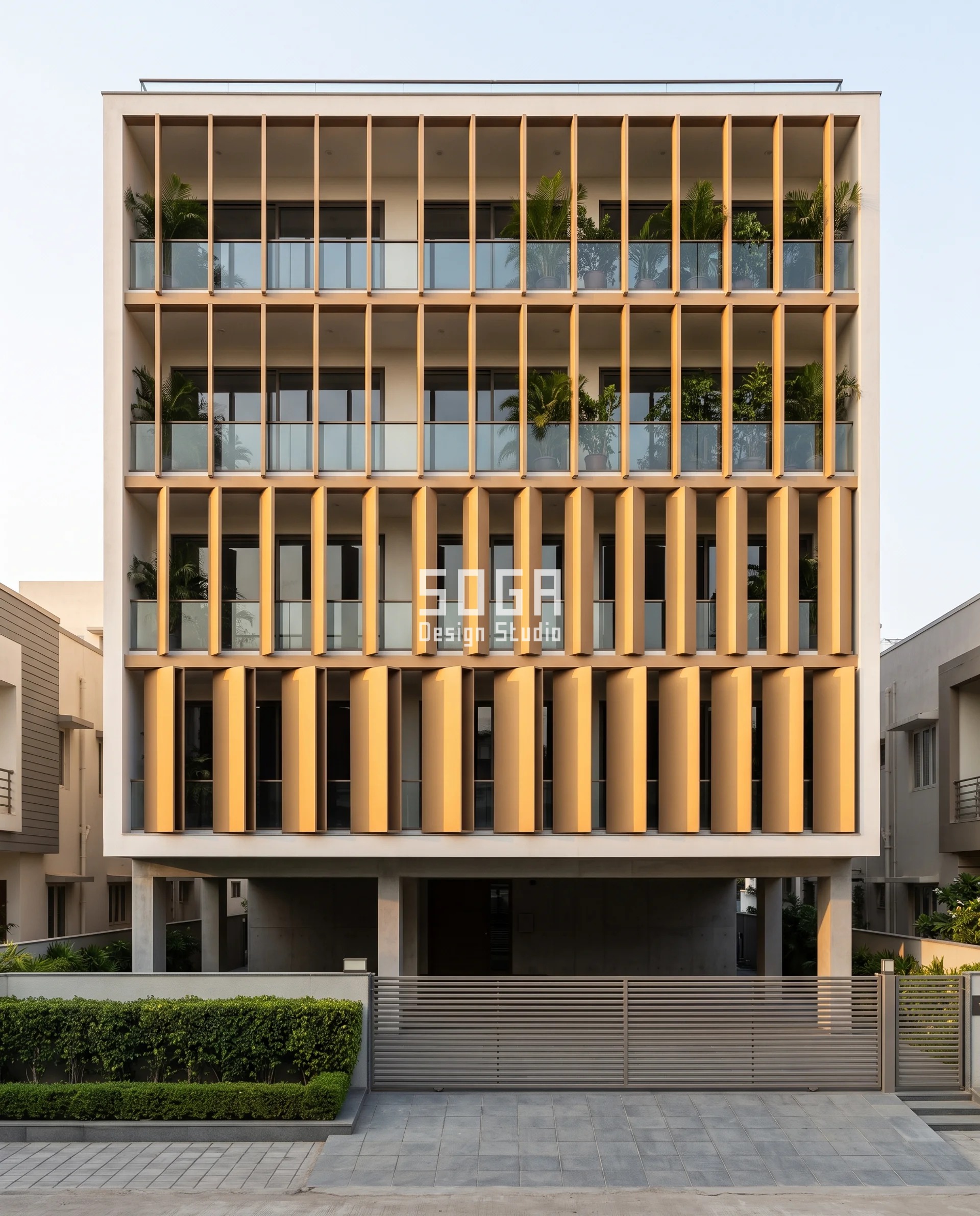
Nizamabad’s west face gets the problem in its purest form. Parametric Throat Blade is a G+4 in Khanapur on a 7.0 m frontage with party walls both sides, and the only open face takes a 3.5–5 m/s pre-monsoon gust that arrives obliquely, carrying dust, at the same hours the 21 May sun sits on that wall at 9.5° of altitude and 18° off the wall normal. Both the dust and the glare come in at an angle. The screen is a bank of press-braked blade boxes, 40 mm on the face, at 150 mm centres, with a 110 mm clear gap. That gap is 110 mm on the fourth floor and 110 mm on the first. The centres are 150 mm everywhere. Head-on free area is 42.0 per cent over the full bay, framing included, on every floor. Nothing you can measure from the street in two dimensions changes at all. What changes is the third dimension. Blade plan-depth runs 90 mm at the parapet band, then 175 mm, 260 mm, and 340 mm at the first floor. A slot of clear gap g and depth d passes only rays inside atan(g/d) of its own normal, so the acceptance cone goes ±50.7° at 90 mm, ±32.2° at 175 mm, ±22.9° at 260 mm and ±17.9° at 340 mm. Same hole, a quarter of the angle. A 110 mm gap 90 mm deep is a hole. The same 110 mm gap 340 mm deep is a short duct with a heading, and an oblique dusty gust does not fit down it — it is turned away at the mouth, while air arriving near square walks straight in. That is the whole difference between admitting and aiming, in one building. All four plan depths come off one press brake tool, because depth here is a fold dimension and not a new part. The boxes are 2.5 mm 5052-H32 in a desert-camel matte 70 per cent PVDF, hung top and bottom off a concealed carrier rail blind-fixed through serrated brackets to 100 × 50 × 4 mm hot-dip galvanised MS SHS at 1200 mm centres on cast-in slab-edge channels. The stilt under the building is left open and unparked, which is where the ground-floor rooms find their air.
| Specification | Parametric Throat Blade |
|---|---|
| Product | SOGA blade box screen — 40 mm face by 90/175/260/340 mm plan-depth press-braked 2.5 mm 5052-H32 boxes at 150 mm centres with a 110 mm clear gap, 42.0 per cent free area on every floor, hung top and bottom off a concealed carrier rail blind-fixed through serrated brackets to 100 × 50 × 4 mm hot-dip galvanised MS SHS at 1200 mm centres on cast-in slab-edge channels, one fixed point per rail with slotted holes and nylon bushes elsewhere, 3 mm EPDM isolation pad and A4 stainless at every steel interface, 12 mm open movement joint every 5.4 m |
| Module | 40 mm face by variable 90/175/260/340 mm plan depth, 150 mm centres, 110 mm clear gap, press-braked 2.5 mm 5052-H32, 70 per cent PVDF desert-camel matte |
| What varies | Blade plan-depth, 90 mm at the parapet band to 340 mm at the first floor — acceptance cone ±50.7° down to ±17.9° |
| Head-on free area | 42.0 per cent head-on, identical on all five floors |
| Indicative rate | ₹1,150 – ₹1,850 per sq ft, supply and install, August 2026 |
Parametric Scoop Course
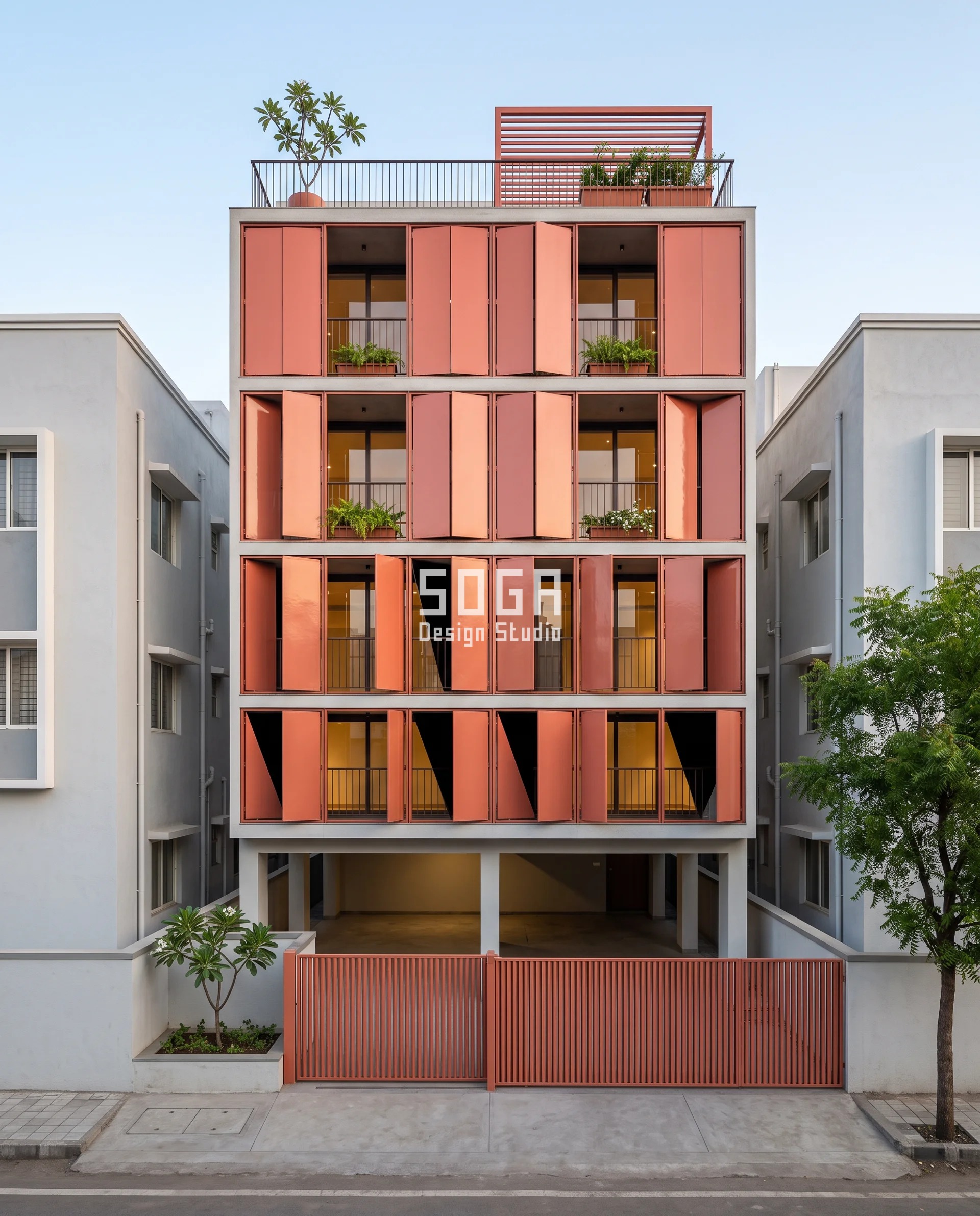
Sangli has one usable air movement and it runs the wrong way. Parametric Scoop Course is a G+3 in Vishrambag on a 6.6 m frontage. The morning easterly is 1.5–2.5 m/s and it runs along the face rather than at it, and on 21 April at 07:00 the sun sits at 10.3° of altitude and 9° off the east normal, which is near enough parallel to the wall as well. A flush window in a stream that runs along a wall sits inside the wall’s own separation layer and captures very little of it. The name is about what the course does, not what the plate is: every plate here is dead flat, with crisp straight edges. The plate is 840 × 2,400 mm of 1.5 mm steel with a 45 mm return, vitreous enamel fired at 820 °C in coral clay, hinged on one vertical edge and standing open like a casement left ajar. Plates sit at 900 mm horizontal centres with a constant 60 mm shadow gap in the closed plane, in 2,460 mm courses. The openable aperture behind the course is held at 18.0 per cent of the bay on every floor, top to bottom. What varies is the swing. Zone by zone the plates are cocked 0°, 7°, 14°, 20° and 26° out of plane, and for a stream running parallel to the wall the catch of a flat plate goes with the sine of that angle. A 0.84 × 2.40 m plate is 2.016 sq m of face, and at 0° it catches nothing at all — it lies in the plane and the air goes past it. At 7° it catches 0.25 sq m, at 14° 0.49 sq m, at 20° 0.69 sq m, and at 26° 0.88 sq m, which is 43.8 per cent of its own area, taken out of air that never changed speed. The free edge of a 26° plate also stands 368 mm clear of the wall plane, so each plate is a small wing wall as much as it is a shade. A flush plate leaves its gap lying parallel to the flow. A swung plate presents a face to it. Turning a plate also turns its drainage, and that is where this system is won or lost. At 26° the lowest free corner becomes the collection point for everything above it, 300 mm from a 60 mm shadow gap, so the 45 mm return is stopped 20 mm short at that corner and a 12 × 10 mm drip notch is cut into it — water then leaves at a point instead of tracking back along the return and into the gap.
| Specification | Parametric Scoop Course |
|---|---|
| Product | SOGA hinged enamel plate — 840 × 2,400 mm flat 1.5 mm steel with a 45 mm return, vitreous enamel fired at 820 °C, hinged on one vertical edge, 900 mm horizontal centres, 60 mm shadow gap all round in the closed plane, 2,460 mm course height, openable aperture behind the course held at 18.0 per cent of the bay, on a two-clip adjustable-tilt bracket set on site from a jig, 3 mm EPDM isolation pad and nylon-bushed A4 stainless at every dissimilar-metal interface, the 45 mm return stopped 20 mm short at the low free corner with a 12 × 10 mm drip notch cut into it |
| Module | 840 × 2,400 mm flat plate, 1.5 mm vitreous enamelled steel fired at 820 °C, 45 mm return, hinged on one vertical edge, 900 mm centres, 60 mm shadow gap, 2,460 mm course |
| What varies | Out-of-plane swing, 0° at the top course to 26° at the first floor — catch 0 to 0.88 sq m per plate |
| Head-on free area | 18.0 per cent openable aperture behind the plate course, identical on all four floors |
| Indicative rate | ₹1,600 – ₹2,600 per sq ft, supply and install, August 2026 |
Parametric Prow Reach
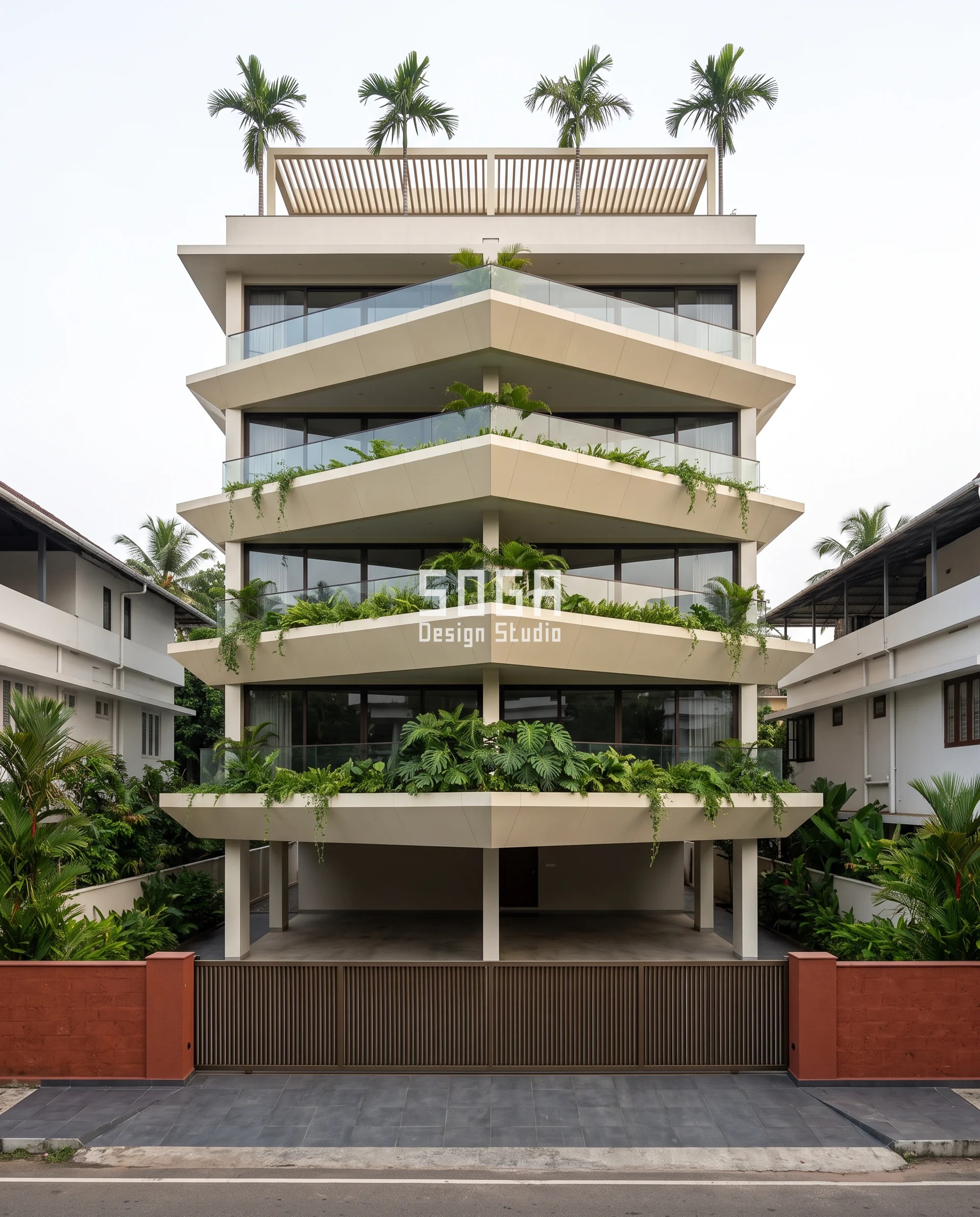
Kollam’s problem is that the wind is over the roof, not on the wall. Parametric Prow Reach is a G+5 in Kadappakada, 18.6 m tall on a 9.0 m street, which gives a canyon aspect ratio H/W of 2.07. Past roughly 0.7 a street goes into skimming flow: the moving air rides across the top of the canyon and the lower facade sees something like a fifth to a third of it. The top floor is standing in clean air. The first floor is sitting inside a slow recirculating vortex, and no amount of opening area on that floor changes what is being offered to it. So the reach is what varies. Every prow is a faceted V in plan at a constant 22° half-angle, moulded in 6 mm sesame-cream gelcoat over GRP top-hat ribs on a 1200 mm module, with a 900 mm frameless glass balustrade inboard and a 2.55 m clear opening height on every floor. The run-out goes 600 mm at the fifth floor, then 860, 1,120, 1,385 and 1,650 mm at the first. Half-angle constant. Module constant. Opening height constant. One quantity moves, and it moves because the air on that floor is further away. At 1,650 mm and 22°, each prow opens 667 mm of plan on each flank, which against a 2.55 m opening height is 4.21 sq m of windward cheek — and 4.21 sq m of leeward cheek sitting in suction on the other side. Single-sided flow scales with the square root of the pressure difference between those two cheeks, so a prow that reaches into faster air is not buying a linear improvement. It is buying the difference between two surfaces that are no longer at the same pressure. This is the wing-wall trick with a mould instead of a mason. All five run-out lengths come off ONE nose mould and one half-angle, cut back to length, and bolt through bonded stainless inserts in the ribs to galvanised steel outriggers on cast-in slab-edge channels. Because a prow is measured on developed area rather than on elevation, it is also the most expensive of the five per square foot. It is the right answer where the canyon is deep and there is front margin to spend it in, and the wrong answer on a 3 m setback where 1,650 mm of reach would sit over the boundary.
| Specification | Parametric Prow Reach |
|---|---|
| Product | SOGA GRP prow shell — 1200 mm module, 6 mm gelcoat laminate over GRP top-hat ribs, constant 22° prow half-angle, run-out 600/860/1,120/1,385/1,650 mm, all five lengths off ONE nose mould, bolted through bonded stainless inserts in the ribs to galvanised steel outriggers on cast-in slab-edge channels, 900 mm frameless glass balustrade inboard, 2.55 m clear opening height on every floor |
| Module | 1200 mm faceted V prow shell, 6 mm gelcoat over GRP top-hat ribs, constant 22° half-angle, 2.55 m clear opening height |
| What varies | Prow run-out, 600 mm at the fifth floor to 1,650 mm at the first — windward cheek 1.53 to 4.21 sq m |
| Head-on free area | Open prow balcony — 900 mm frameless glass balustrade, 2.55 m clear opening height on every floor |
| Indicative rate | ₹1,900 – ₹3,100 per sq ft of developed area, supply and install, August 2026 |
Parametric Vane Pitch
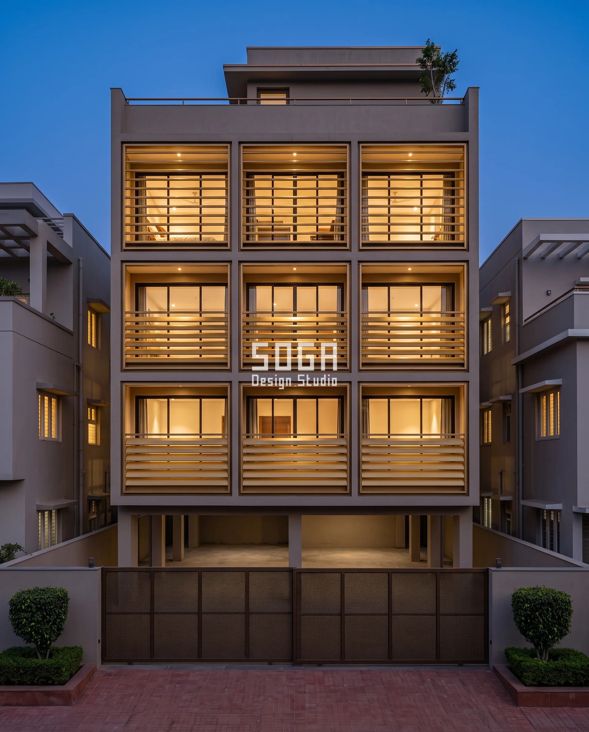
Muzaffarpur’s air arrives, and then it leaves over your head. Parametric Vane Pitch is a G+3 in Mithanpura at 26.12° N, where the usable May–June easterly is a weak, variable 1–2 m/s. The vane bank centres 2.10 m above finished floor. A person sits, stands and sleeps between 0.6 m and 1.6 m. Air leaves a louvre bank on the blade’s own heading, so where the bank points decides everything, and a bank pointing level hands the whole street’s air to the ceiling and takes it straight back out of the top of its own opening. The vane is a 50 × 150 mm 6063-T6 aerofoil at 120 mm centres in a 1200 × 2400 mm welded steel cassette, honeycomb-gold super-durable polyester, one extrusion die and one cassette size across the whole building. The openable aperture behind the bank is held at 58.0 per cent of the bay, top to bottom — and that figure is the window behind the screen, not the elevational openness of the screen itself. Every vane sits on a rotatable end-bearing and the angle is set and locked on site. The angle is the only site variable on this facade. It is specified 0–14° across the top band, 18–30° at mid height and 32–44° at the first floor. Landing depth is (2.10 − 1.10) divided by the tangent of the angle, so the stream crosses 1.10 m above the floor at 4.01 m in at 14°, 3.08 m at 18°, 1.73 m at 30°, 1.60 m at 32° and 1.04 m at 44°. At 0° it never enters the occupied zone at all. One rotation. Not one component changed. Turning vanes closes the throat between them: 70.0 mm at 0°, 66.4 mm at 14°, 53.9 mm at 30° and 36.3 mm at 44°, which takes the net throat area of a cassette from 1.68 sq m to 0.87 sq m. The aperture behind stays at 1.67 sq m. So at the first floor the throat, not the window, is the smaller opening — deliberately. On a face being offered 1–2 m/s, direction is worth more than area, and this facade is supply-limited, never throat-limited. Head-on it does not read as a gradient of angle, and it is worth being honest about that. A 150 mm chord at 120 mm centres has closed the elevation by about 30°, so what the street actually reads is banks growing taller and heavier as the building comes down, with the interiors visible on all three floors at dusk. The bank that looks most shut is doing the most work on the building.
| Specification | Parametric Vane Pitch |
|---|---|
| Product | SOGA aerofoil vane bank — 50 × 150 mm 6063-T6 aerofoil vanes at 120 mm centres in a 1200 × 2400 mm welded-steel louvre cassette, super-durable polyester powder coat, rotatable end-bearing at each vane with the angle set and locked on site, cassette hung on four cast-in brackets per bay, openable aperture behind the bank held at 58.0 per cent of the bay on every floor, one extrusion die and one cassette size throughout with the angle the only site variable |
| Module | 50 × 150 mm aerofoil vane at 120 mm centres in a 1200 × 2400 mm welded-steel cassette, 6063-T6 extrusion |
| What varies | Vane angle, 0–14° on the top band to 32–44° at the first floor — landing depth 4.01 m down to 1.04 m |
| Head-on free area | 58.0 per cent openable aperture behind the bank, identical on all three floors; throat 70.0 mm down to 36.3 mm |
| Indicative rate | ₹1,250 – ₹2,100 per sq ft, supply and install, August 2026 |
Parametric Braid Stand
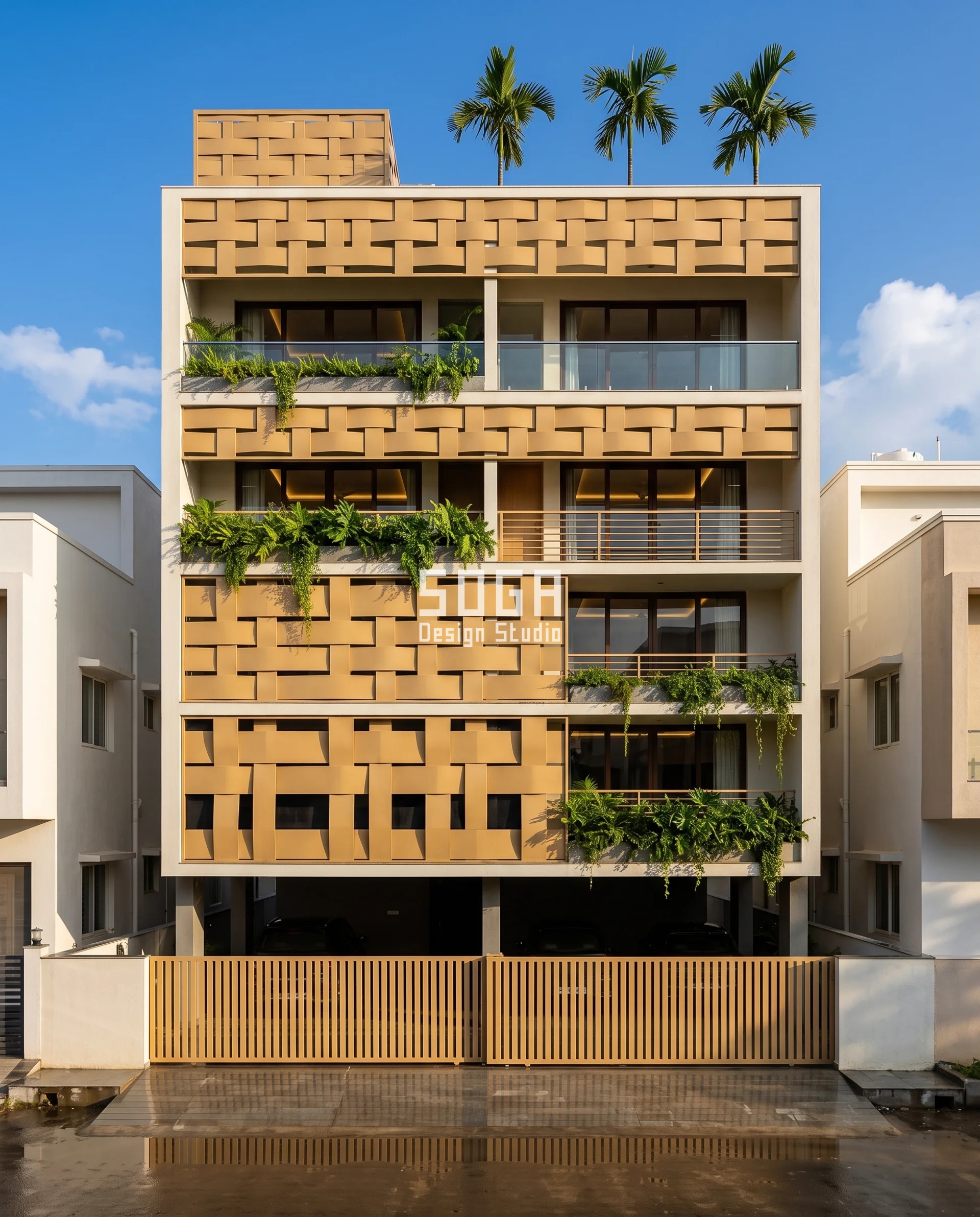
Shivamogga’s screen has to sort water from air. Parametric Braid Stand is a G+4 in Vinoba Nagar on the Malnad edge at 13.93° N — the district long-period average is about 1,814 mm and the western taluks run well past 2,500 mm — and the rain arrives on a 3–5 m/s south-westerly, sideways rather than falling. The load-bearing number here was never the annual total. It is the angle. The weave takes the upper band across the frontage and shares the three lower bands with the balconies, so the ribbons stand in front of an open edge rather than draping the whole face. The ribbon is a 400 mm wide roll-formed box section in 1.2 mm ZM310 zinc-magnesium coated steel with a sunflower-tan PVDF finish, woven at a 900 mm pitch both ways over a 500 × 500 mm open cell — 31.0 per cent free area on every band. What varies is the crossing depth: how far the over-ribbon stands proud of the under-ribbon at each intersection. 60 mm at the parapet, 155 mm, 250 mm, and 340 mm at the first floor. Two numbers set that. Geometry first: a 2 mm drop falls at about 6.5 m/s, so on a 4 m/s wind it arrives 31.6° off vertical, and covering a 500 mm cell against that angle takes 308 mm of horizontal overhang. That is why the wet bands are 340 mm and not 250 mm. Then inertia: the Stokes number of a 1 mm drop at 4 m/s across a 400 mm ribbon is about 31, and above 1 a droplet cannot follow a streamline that turns. At a 60 mm crossing the sheet of air stays attached, barely turns, and the rain rides straight through with it. At 340 mm the crossing is 68 per cent of the cell, the shear layer separates, the air turns — and the water, with a Stokes number thirty times too high to turn with it, lands on the ribbon and runs off. Identical 31.0 per cent opening on both bands. Opposite wet-season result. Every crossing genuinely alternates over and under, with a concealed cleat at each intersection, on a 500 mm standoff carrier of hot-dip galvanised SHS off the slab edge. A faked lap — two ribbons butted and capped to look woven — is the failure mode on this system, and it is visible from the street on a wet day, because the water sheet does not break where it should.
| Specification | Parametric Braid Stand |
|---|---|
| Product | SOGA woven ribbon screen — 400 mm wide roll-formed box section in 1.2 mm ZM310 zinc-magnesium coated steel with PVDF finish, 900 mm weave pitch both ways, 500 × 500 mm open cell, 31.0 per cent free area everywhere, crossing depth 60/155/250/340 mm over four bands, on a 500 mm standoff carrier of hot-dip galvanised SHS off the slab edge, every crossing genuinely alternating over-under with a concealed cleat at each intersection |
| Module | 400 mm wide roll-formed ribbon in 1.2 mm ZM310 coated steel, 900 mm weave pitch both ways, 500 × 500 mm open cell |
| What varies | Crossing depth, 60 mm at the parapet band to 340 mm at the first floor — 12 per cent to 68 per cent of the cell |
| Head-on free area | 31.0 per cent head-on, identical on all four bands |
| Indicative rate | ₹1,050 – ₹1,750 per sq ft, supply and install, August 2026 |
How an Aiming Screen Is Actually Fixed to the Building
All five hang off the same family of parts, and that is the point. Cast-in slab-edge channels, a hot-dip galvanised MS SHS carrier at 100 × 50 × 4 mm on 1200 mm centres, and a bracket that lets the module be set on site. The varied quantity in each building — plan-depth, tilt, run-out, vane angle, crossing depth — is a fold dimension, a bracket setting or a cut length, and never a new part number. Nizamabad’s four plan depths come off one press tool. Kollam’s five run-outs come off one nose mould. Muzaffarpur runs one extrusion die and one cassette size across three storeys and sets the angle at the bearing. That is what makes a gradient affordable: the gradient lives in the assembly, not in the tooling. A facade that needs five moulds to make five depths is a facade nobody builds. Wind is designed to IS 875-3:2015, and a screen standing 340 mm to 1,650 mm off the wall is not a cladding panel. It is a projecting element with pressure on one face, suction on the other, and a real moment at the bracket — a Kollam prow at 1,650 mm of run-out puts its load a long way from the slab edge, which is why it gets a galvanised outrigger and not a clip. The slab-edge channel is cast in with the frame, at a stage most owners have already passed by the time they start talking about the elevation. Retrofitting a chemical anchor into a 150 mm slab edge is possible, but it changes the bracket, the fixing schedule and the price, and it is the single most common reason a screen like this gets flattened out during value engineering.
| Design parameter | Specification |
|---|---|
| Plot frontage | 6.6 – 9.0 m across the five concepts, party walls both sides, front the only open face |
| Open faces | 1 of 4. Side and rear built to the plot line on all five |
| Floor-to-ceiling height | 3.0 m clear on every floor of all five concepts |
| Front room depth designed to | 6.0 m with a single opening; 7.5 m where a high and low opening are paired |
| Held constant per building | Opening size, pitch and spacing — top floor to first, without exception |
| Quantity varied per building | Exactly one: blade plan-depth, plate swing, prow run-out, vane angle or crossing depth |
| Head-on free area | 42.0 per cent (Nizamabad), 31.0 per cent (Shivamogga); 18.0 per cent aperture behind the plate course (Sangli), 58.0 per cent aperture behind the vane bank (Muzaffarpur); Kollam is an open prow balcony |
| Substructure | 100 × 50 × 4 mm hot-dip galvanised MS SHS at 1200 mm centres on cast-in slab-edge channels |
| Dissimilar-metal isolation | 3 mm EPDM pad and nylon-bushed A4 stainless at every steel-to-light-alloy interface |
| Thermal movement | One fixed point per rail, slotted holes elsewhere, 12 mm open movement joint every 5.4 m |
| Insect mesh | 16-mesh fibreglass, 60–65 per cent free area, Cd about 0.5–0.6 — clip-in at the inner window leaf, never over the screen |
| Cleaning access | From inside the balcony or off the carrier standoff — 500 mm at Shivamogga, 600–1,650 mm of prow at Kollam |
| Wind design | IS 875-3:2015, treated as a projecting element with pressure and suction on opposite faces |
| Mode of operation | Mixed-mode. Front bays close on a sliding glassline for the 4–6 peak monsoon weeks and the worst pre-monsoon dust weeks |
The three details that decide whether any of it survives
- Water at the Sangli plate, where the swing is doing the work. Swing a flat enamelled plate 26° out of plane and its lowest free corner becomes the collection point for the whole plate above it, 300 mm from a 60 mm shadow gap. So the 45 mm return is stopped 20 mm short at that corner and a 12 × 10 mm drip notch is cut into it, forcing the water to leave at a point instead of tracking back along the return and into the gap. The two-clip bracket gets a 3 mm EPDM isolation pad and nylon-bushed A4 stainless bolts at every interface — vitreous enamel is fired onto steel at 820 °C and the bracket is a light alloy, which is a bimetallic couple standing in monsoon runoff. Nothing on an enamelled panel can be touched up on site. It is right the first time or it is a replacement panel.
- Movement at the Nizamabad carrier rail. The blade boxes are press-braked 2.5 mm 5052-H32 — all four plan depths, 90 through 340 mm, come off one tool, because depth is a fold dimension — and they hang top and bottom off 100 × 50 × 4 mm hot-dip galvanised MS SHS rails at 1200 mm centres on cast-in slab-edge channels. The alloy moves at 23.8 microstrain per kelvin. A west face in Telangana swings 40 K between a May afternoon and a January dawn, which over a 6.0 m rail is 5.7 mm of travel. So: one fixed point per rail, slotted holes and nylon bushes everywhere else, and a 12 mm open movement joint every 5.4 m. Skip it and the 110 mm gaps stop being 110 mm gaps by the third summer — and the acceptance cone the whole design rests on goes with them.
- Where the insect mesh goes, which is the detail that quietly undoes all of the above. A standard 16-mesh fibreglass insect screen runs roughly 60–65 per cent free area at a discharge coefficient near 0.5–0.6. Stretch it across the aiming geometry — the blade bank, the vane cassette, the weave — and you have put that loss in front of the whole instrument and blurred the heading it took 340 mm of depth to establish. The mesh belongs on the inner window leaf, in a clip-in removable cassette at the smallest aperture in the chain, downstream of the aiming, where it costs the same percentage of a much smaller number and can be taken out and washed.
The Honest Limit: Past 7.5 m the Facade Cannot Do It
A room deeper than about 7.5 m cannot be ventilated from the front facade alone, whatever the screen does. CIBSE AM10 puts single-sided natural ventilation at roughly 2.0 times the floor-to-ceiling height with one opening and 2.5 times with a high and low pair, which at a 3.0 m ceiling is 6.0 m and 7.5 m of usable depth, and it caps the arrangement near 10 m regardless. It is worth saying plainly that the code is deliberately conservative and measured work disagrees with it — AIVC experimental studies have found effective penetration past 2.5 times the ceiling height, some beyond 3.0. That is a live disagreement, not a licence, and it moves the number by about a metre, not by five. So on a 15 m deep narrow plot with a single 6 m front room, everything above works. On the same plot with one 12 m room running front to back, none of it does. Facade geometry aims air; it cannot manufacture a pressure difference that does not exist. Past 7.5 m the honest answer is a second opening, and it costs floor area: a light well, an open-to-sky court, or the stair shaft worked as a chimney with an openable head. And for the four to six weeks of peak monsoon at Kollam and Shivamogga, and the worst pre-monsoon dust weeks at Nizamabad, the front bays close on a sliding glassline and the rooms run on fans and dehumidification. Mixed-mode, on a schedule, not as an ideology. All five buildings in this post are SOGA concepts, not built work — the engineering is the claim, not the photograph.
What Does an Air-Aiming Facade Cost per Sq Ft in India (2026)?
Between ₹1,050 and ₹3,100 per sq ft installed, depending on the system and the access, with the geometry that does the aiming accounting for ₹180 to ₹420 of it. These are indicative August 2026 rates, supply and install, itemised per project. Bands widen with height, access and run length — a five-storey narrow frontage with no crane standing room prices differently from the same area at ground level, and a prow measured on developed area prices differently again from a flat screen measured on elevation. The rates were re-verified this run against current Indian market benchmarks; nothing here is inherited from an earlier post. Every figure is a range, and it stays a range until there is a drawing, a frontage dimension and a site to stand on.
| System / material | Indicative rate (per sq ft) |
|---|---|
| S1 Nizamabad — press-braked 2.5 mm 5052-H32 blade boxes, 70 per cent PVDF, concealed carrier rail | ₹1,150 – ₹1,850 per sq ft |
| S2 Sangli — 1.5 mm vitreous enamelled steel plates fired at 820 °C, hinged on adjustable-tilt brackets | ₹1,600 – ₹2,600 per sq ft |
| S3 Kollam — 6 mm gelcoat GRP prow shells on galvanised slab-edge outriggers, measured on developed area | ₹1,900 – ₹3,100 per sq ft |
| S4 Muzaffarpur — 6063-T6 aerofoil vane extrusion, super-durable polyester, welded steel cassette, rotatable end-bearings | ₹1,250 – ₹2,100 per sq ft |
| S5 Shivamogga — roll-formed 1.2 mm ZM310 ribbon, PVDF, 500 mm standoff carrier, genuine over-under weave | ₹1,050 – ₹1,750 per sq ft |
| Hot-dip galvanised MS substructure, cast-in slab-edge channels, brackets and isolation pads — inside the bands above, itemised separately at | ₹280 – ₹520 per sq ft |
| THE AIMING PREMIUM — what the third dimension costs over a flat screen of identical free area: extra plan depth, deeper carrier standoff, slab-edge outriggers and the on-site setting of tilt or angle | ₹180 – ₹420 per sq ft |
| Clip-in removable insect mesh cassette at the inner leaf, 16-mesh fibreglass in a light-alloy frame | ₹110 – ₹240 per sq ft of opening |
The Five Systems Side by Side: What Was Held Constant
Read the right-hand column first, because the constants are the argument. In each building the opening size, the pitch and the spacing are identical from the top floor to the first, so the only thing that could have changed the result is the one quantity named on the left. Guides on this subject usually change several things at once and attribute the outcome to none of them.
Across the set there are five different quantities in three different units — millimetres of depth, degrees of rotation, millimetres of projection — and all of them do the same job. They decide the heading of the stream after it crosses the wall plane. That is the claim this whole post makes, and it is why the five are published together rather than as five separate concepts.
| Project, city and quantity moved | Range, what was held constant, and what it serves |
|---|---|
| Parametric Throat Blade — Nizamabad, blade plan-depth | 90 → 340 mm. Constant: 110 mm clear gap, 150 mm centres, 40 mm face, 42.0 per cent free area. Acceptance cone ±50.7° → ±17.9°. Serves a 6.0 m front room. |
| Parametric Scoop Course — Sangli, plate swing | 0° → 26°. Constant: 840 × 2,400 mm plate, 900 mm centres, 60 mm shadow gap, 18.0 per cent aperture behind. Catch 0 → 0.88 sq m per plate. Serves a 6.0 m front room. |
| Parametric Prow Reach — Kollam, prow run-out | 600 → 1,650 mm. Constant: 22° half-angle, 1200 mm module, 2.55 m opening height. Windward cheek 1.53 → 4.21 sq m. Serves a 7.5 m front room with a high and low pair. |
| Parametric Vane Pitch — Muzaffarpur, vane angle | 0–14° → 32–44°. Constant: 50 × 150 mm vane, 120 mm centres, 1200 × 2400 mm cassette, 58.0 per cent aperture behind. Landing depth 4.01 → 1.04 m. Serves a 6.0 m front room. |
| Parametric Braid Stand — Shivamogga, crossing depth | 60 → 340 mm. Constant: 400 mm ribbon, 900 mm weave pitch, 500 × 500 mm cell, 31.0 per cent free area. Rain overhang required 308 mm at 31.6°. Serves a 6.0 m front room. |
Does NBC 2016’s 10 Per Cent Openable Area Ventilate the Room?
No. It is a lower bound on area, and it says nothing about where the air goes after it enters. NBC 2016 Part 8 requires openable area of at least 10 per cent of floor area in habitable rooms, and warm-humid coastal practice commonly pushes this to 15–20 per cent. Meeting that minimum does not ventilate a single-sided room. On a 4.0 × 6.0 m bedroom the code number is 2.4 sq m of openable area, which is one large window — and a 6 m room behind one large window on one face is exactly the case CIBSE AM10 describes as being at its limit.
The other Indian instruments say similar things in different units. IS 3362:1977 covers natural ventilation of residential buildings, and Eco-Niwas Samhita 2018, the residential envelope code, asks a naturally ventilated dwelling for an openable window-to-floor area ratio of at least 12.5 per cent in most climate zones. All of them are area rules. None of them is a direction rule. There is no clause anywhere in Indian practice that asks what heading the incoming stream takes, which is exactly why the question never gets asked on site.
Then there is the gap between openable area and effective area, which is where a great deal of drawn ventilation quietly disappears. An opening’s flow is its area multiplied by a discharge coefficient (Cd), and every layer in the chain multiplies again. A 16-mesh fibreglass insect screen is 60–65 per cent free area at a Cd near 0.5–0.6. A security grille takes another slice. Put a screen, a mesh and a grille in series and 0.60 × 0.55 × 0.75 leaves you about a quarter of the area on the drawing. The order matters as much as the count: losses upstream of the aiming geometry blur the heading, losses downstream of it do not.
Free area and effective area are also not the same thing as the aperture behind a screen, and the three get quoted interchangeably. At Muzaffarpur, 58.0 per cent is the openable window behind the vane bank, held constant on every floor. The elevational openness of the bank itself falls away as the vanes turn, because a 150 mm chord at 120 mm centres has closed the elevation by about 30°. Quoting one number when you mean the other is the most common specification error on screened facades, and it is worth settling in the first meeting rather than at handover.
| Area rule or loss | What it is worth on a 4.0 × 6.0 m room |
|---|---|
| NBC 2016 Part 8, habitable room | Openable area at least 10 per cent of floor area — 2.4 sq m |
| Eco-Niwas Samhita 2018, naturally ventilated dwelling | Openable window-to-floor area ratio at least 12.5 per cent — 3.0 sq m |
| Warm-humid coastal practice | 15–20 per cent openable — 3.6 to 4.8 sq m |
| 16-mesh fibreglass insect screen | 60–65 per cent free area, Cd about 0.5–0.6 |
| Effective area, mesh clipped to the inner leaf | 2.4 sq m × 0.62 free area × 0.55 Cd, about 0.82 sq m effective — heading intact |
| Effective area, mesh stretched over the screen | The same 0.82 sq m, but the loss sits upstream — the heading 340 mm of depth bought is blurred |
| Screen plus mesh plus security grille, in series | 0.60 × 0.55 × 0.75 = 0.25 of the drawn area |
Which Way Should the Front Face When the Plot Has Decided?
You cannot rotate the plot, so rotate the module instead. On a party-wall plot the front orientation was fixed by the layout somebody drew twenty years ago, and every honest answer starts from there rather than from a wind rose. What is still yours to choose is the third-dimension quantity: tilt, angle and run-out are all set at the bracket on site, which means the same extrusion and the same cassette serve a north front and an east front at different settings.
The prevailing wind still matters, because it tells you which of the five moves to reach for. A face that gets its air square wants depth, for filtering and for glare rejection. A face that gets its air along the wall wants catch — tilt or reach. A face deep in a canyon wants reach and nothing else. A face with weak air and a comfort problem wants angle, aimed at 1.10 m above the floor. And a face on a coast in the monsoon wants separation before it wants anything else at all.
Two practical notes on Indian streets. First, the plotted grid usually runs north-south or east-west, so most narrow-plot fronts land within about 15° of a cardinal direction, and there is a real difference between a south front in Chennai and a west front in Ahmedabad that no single screen will cover. Second, the neighbour’s building height changes your canyon: an H/W of 2.07 at Kollam becomes a different number the year the plot opposite goes up two more floors, which is an argument for reach that is generous rather than exact.
| Climate zone and typical cities | What the front face is being offered, and which quantity to move |
|---|---|
| Warm-humid coast — Kollam, Chennai, Mumbai | Afternoon onshore sea breeze, often above roof level in a canyon; 15–20 per cent openable. Move reach: prow run-out 600–1,650 mm |
| Composite — Muzaffarpur, Kolkata, the Ganga plain | Weak variable 1–2 m/s May–June easterlies. Move angle: vane pitch 32–44° on the lower floors, aimed at 1.10 m |
| Hot-dry — Ahmedabad, and Nizamabad’s pre-monsoon weeks | 3.5–5 m/s dusty oblique gusts plus low-altitude west sun. Move depth: blade plan-depth 260–340 mm, with the night purge routed through the stair |
| Moderate upland — Shivamogga, Pune, Bengaluru | 3–5 m/s monsoon south-westerlies, rain arriving 31.6° off vertical. Move crossing depth: 340 mm on the wet bands |
| Hot-dry to composite inland — Hyderabad, Sangli | One weak usable movement, usually a morning easterly at 1.5–2.5 m/s running along the wall. Move swing: plate tilt out to 26° |
| Any zone, orientation fixed by the plot | Rotate the module, not the building. Tilt, angle and run-out are site settings on the same part, so one die serves every orientation |
What Do You Do When Cross Ventilation Is Impossible?
You buy a second opening from inside the plot, and it costs floor area. Past about 7.5 m of room depth the front face is finished, and there are exactly three honest fallbacks: an open-to-sky court, a light well, and the stair shaft worked as a chimney. All three do the same thing — they create a second pressure, which is the one thing facade geometry cannot manufacture.
The court is the one people dismiss on cost and should not. On a 7.62 × 15 m plot, a 3.0 × 3.0 m open-to-sky court is 9.0 sq m — 7.9 per cent of the plot, 97 sq ft per floor. The 1.2 m side setback that most owners are told to leave is 18.0 sq m, 194 sq ft per floor. The court costs half of what the setback costs and it actually delivers a second opening, because it is open to the sky and develops its own stack, while a 1.2 m slot between two blank walls is a stagnant column. If you are going to give up floor area, give it up where it does something.
The stair shaft is the cheapest of the three, because you already own it. A 10.5 m shaft with a 6 K inside-to-outside difference develops about 2.5 Pa of stack pressure, which through a 1.2 sq m openable head at a discharge coefficient near 0.6 is roughly 1.2 m/s of exhaust. That is the route the Nizamabad night purge takes when the first-floor panel is too deep to accept it. The condition is that the shaft must be open to the floors it serves and openable at the top. A sealed fire lobby with a fixed rooflight is a stair, not a chimney.
A light well works only above a certain width. As a rough rule, once the well is narrower than about a third of its own height it stops behaving as an open face and becomes a stagnant column with a little daylight in it. On a G+3 that means roughly 2.5 to 3.0 m clear before it is worth the floor area, which is why the 1.2 m setback keeps disappointing people who were promised airflow. And where none of the three is available — a deep plot, a fixed plan, an existing house — the answer is a high-level clerestory or transom ventilator paired with the low front window, which is precisely what buys 7.5 m instead of 6.0 m, and then mechanical assistance beyond that.
What quietly kills the flow after everything is drawn correctly
- Insect mesh stretched over the aiming geometry instead of clipped into the inner leaf — 60–65 per cent free area at a Cd of 0.5–0.6, applied to the whole instrument rather than to the smallest aperture in the chain.
- Thermal movement never detailed: 5.7 mm of travel over a 6.0 m rail across a 40 K swing, and the 110 mm gaps are not 110 mm gaps by the third summer.
- A faked over-under lap in a woven screen. The water path is only real if every crossing genuinely alternates, and a butted-and-capped joint shows from the street on a wet day.
- Three restrictions in series — screen, mesh and a security grille. 0.60 × 0.55 × 0.75 leaves about 25 per cent of the area on the drawing.
- A wardrobe run across the room at 3.5 m, standing exactly in the landing zone a 32° vane angle was set for.
- Sealed, non-openable high-level glazing, which removes the outlet half of the high/low pair and takes the room from 7.5 m of usable depth back to 6.0 m.
Related Reading
- parametric facade design in India, and what is actually buildable
- what building facade design covers, end to end
- the SOGA parametric facade systems
- a facade screen that does not make the room dark
- window grill alternatives for Indian houses
- G+3 and G+4 elevation design in India
- reducing road noise with facade depth rather than gaps
- spending the front setback once, properly
Frequently Asked Questions
Can you get cross ventilation on a narrow plot with party walls on both sides?
No. Cross ventilation needs an inlet and an outlet on opposing faces, and a party-wall plot has one open face, so air must enter and leave through the same facade. Enlarging the front windows does not fix it, because the limit is the absence of a pressure difference across the room, not the absence of opening area. What you can do is aim the one opening you have: blade depth from 90 to 340 mm, plate swing to 26 degrees, prow projection to 1,650 mm and vane angle to 44 degrees all change where the incoming stream goes after it crosses the wall plane, without moving the free area by a single percentage point.
How deep can a room be with windows on only one wall?
About 6.0 m with a single opening and about 7.5 m with a paired high and low opening, at a 3.0 m floor-to-ceiling height. CIBSE AM10 puts single-sided ventilation at roughly 2.0 times the floor-to-ceiling height with one opening and 2.5 times with a pair, and caps it near 10 m in any arrangement. AIVC experimental work has measured penetration beyond 2.5 times, some studies past 3.0, so the code is conservative by roughly a metre. Design to 7.5 m anyway.
Does a facade screen block airflow?
A screen with real depth does not block air so much as aim it. Free area sets how much air can pass; blade depth, tilt and projection set the direction the stream takes once it crosses the wall plane. A 110 mm gap 90 mm deep accepts air from within plus or minus 50.7 degrees of its normal, while the same 110 mm gap 340 mm deep accepts only plus or minus 17.9 degrees. Identical free area, a quarter of the acceptance angle. The screen that does block airflow is the one with an insect mesh stretched across the front of it.
How much openable area does NBC 2016 Part 8 require for a habitable room?
At least 10 per cent of the floor area, which is 2.4 sq m for a 4.0 by 6.0 m bedroom, and Eco-Niwas Samhita 2018 asks a naturally ventilated dwelling for an openable window-to-floor area ratio of at least 12.5 per cent. Warm-humid coastal practice commonly uses 15 to 20 per cent. Clearing the minimum makes the drawing legal, not the room ventilated: it is a lower bound on area and says nothing about where the air goes after it enters.
What does an air-aiming facade cost per sq ft in India, and how long does it take?
Rs 1,050 to Rs 3,100 per sq ft installed at August 2026 rates, depending on the system, the material and the access, with the aiming geometry itself accounting for Rs 180 to Rs 420 of that over a flat screen of identical free area. Hot-dip galvanised substructure runs Rs 280 to Rs 520 per sq ft inside those bands. Allow roughly 3 to 5 weeks for design and fabrication drawings and 4 to 8 weeks for fabrication and installation on a narrow-plot G+3 to G+5, longer where slab-edge channels have to be retrofitted rather than cast in.
Send Us the Frontage and the Deepest Room
Two numbers decide most of this: the clear frontage of your plot, and the depth of the deepest room on the front face. Send those, plus the street width and which way the front looks, and we will tell you whether the one open face can carry the room on its own or whether you are buying a second opening — and what each of those costs. SOGA Design Studio designs and engineers parametric facade systems in India, from concept geometry through fabrication drawings and installation detail, for narrow-plot houses in Nizamabad, Sangli, Kollam, Muzaffarpur, Shivamogga and the rest of the country. Write to [email protected]. All five systems on this page are SOGA concepts, not built work.