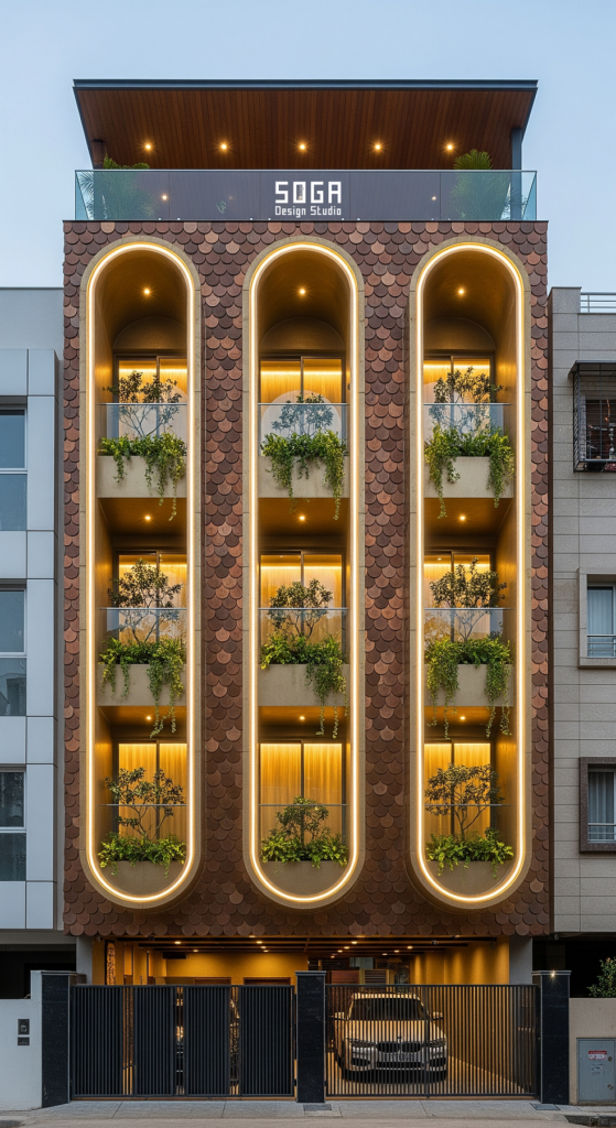
On a house elevation we ask the windows to agree with each other. That is the wrong request, and we keep making it long after the slab is cast.
An uneven-window elevation is a house front where the openings sit at different heights, widths or centre lines because the plan was drawn room by room. It is a positional problem, not a proportional one. Each opening is correct for its room and wrong for the face.
When windows on a house elevation do not line up, do not move them. Hold one constant grid across the face, same member at the same pitch on every floor, and vary only its standoff. A screen 250 to 450 mm off the wall hides the openings beyond about 35 degrees off normal.
Everything below is measured. The five house elevation designs in this post are SOGA concepts drawn for this argument, not built work, and every angle in them is recomputed from one expression rather than carried over from an earlier drawing.
The 2100 mm Lintel Datum Is Correct – Until The Lintel Is Cast
The standard answer is correct, and it is the one we draw too. Hold every opening head on one continuous lintel band at 2100 mm, run the mullions of the upper floor directly over the mullions below, keep the street face between 25 and 35 per cent glass, and the elevation composes itself. That answer costs nothing extra, because the lintel band is being poured anyway. It also has an expiry date nobody states. It is available only until the lintel is cast, and on a G+3 that is week six to week ten of the frame. After the pour the head line is a 150 mm concrete band running the full width of the face, and moving one opening 200 mm means cutting it. The 2100 mm datum is the right answer to a question most readers of this page have already stopped being able to ask. If your drawing is still on paper, take that answer and close this page. The rest of this is for the house that is already standing.
The Kanat: One Constant Screen In Front Of An Irregular Camp
A kanat is the cloth wall of a camp. Identical block-printed or applique panels, every one cut to the same width, laced to a line of poles to make a continuous screen that turns open ground into a courtyard. Mughal camp practice across Delhi, Agra and Lahore used it, and it still goes up at every wedding ground in the country. What matters is the arithmetic of it: the panel pitch belongs to the panel and to nothing behind it. A camp was completely irregular inside – tents of four different sizes, kitchens, animals, service lines – and the kanat gave the outside one constant reading at one constant rhythm, panels overlapping at every seam so the run closed up rather than opened as you walked past it obliquely. That is not decoration. It is the oldest working proof that a constant screen in front is cheaper than agreement behind. One caution on the word: this is the Hindi and Urdu kanat, the canvas enclosure of a tent, not the Persian qanat, the underground water channel. Same transliteration, different word.
The Rule: Choose The Angle, Not The Alignment
Do not make the openings agree. Put one constant grid in front of them – identical member, identical pitch, identical set-out on every floor – and let each room keep the opening it needs. The grid is not a pattern laid over the elevation. It is a datum that replaces the elevation. What you design after that is not a shape. It is the angle at which the wall behind stops being readable, and that angle is a number you choose before you draw anything. Opening size was spent by the room. Pitch was spent by the 3000 mm structural bay. The one quantity nobody has claimed by the time the frame is up is how far the grid stands off the face, and it is available precisely because it belongs to no room. Everything after this heading is the arithmetic of that single choice, worked on five Indian streets.
Why Windows On An Indian House Elevation Never Line Up
Sill height is an ergonomic dimension, not a compositional one, and it is fixed before the front elevation is drawn at all. Seated eye height is about 1200 mm. A bed head is 600 to 750 mm. A kitchen counter is 850 to 900 mm with a 150 mm upstand. Privacy standing requires a toilet ventilator above eye height. None of those four numbers is negotiable after the plan is signed.
Windows on an Indian house elevation rarely line up because sill height is set by the room, not the facade. A living-room sill sits at 450 to 600 mm, a bedroom at 750 to 900 mm, a kitchen at 1050 to 1200 mm, a toilet ventilator above 1800 mm. Four rooms means four sills.
Four rooms on one face is 1350 mm of vertical disagreement, correct in every case, and already built into the plan before anyone opened the elevation sheet. That is why the head line can be saved and the sill line cannot. The 2100 mm lintel band only ever fixed the heads. It never touched the sills, and the sills are where the disagreement actually lives.
| Room on the street face | Required sill height, and what it forces on the elevation |
|---|---|
| Living room | 450-600 mm – so a seated adult at about 1200 mm eye height can see out. Sets the lowest sill on the face. |
| Bedroom | 750-900 mm – clears a bed head at 600-750 mm. Sits 150-450 mm above the living-room sill on the same floor. |
| Kitchen | 1050-1200 mm – clears a 850-900 mm counter plus a 150 mm upstand. Sits 450-750 mm above the living-room sill. |
| Toilet ventilator | Above 1800 mm – so nobody standing outside can see in. Head lands at about 2250 mm, above the 2100 mm lintel band. |
| Stair landing | About 1575 mm above the floor below on a 3000 mm floor-to-floor. Belongs to neither storey. |
| Spread on one face | 1350 mm of sill disagreement across four rooms; 2850-3000 mm clear once the landing window is counted. |
The Stair-Landing Window: The Opening That Can Align With Nothing
Every Indian G+2 and G+3 has one, and no ranking page on this query mentions it. It is the single opening that defeats every alignment hierarchy in the trade.
The stair-landing window cannot be aligned with anything. It sits at half-level between two floors because the landing does, so no head datum, mullion line or sill line on either floor can reach it. It is the single opening that a constant grid in front of the wall exists to absorb.
Put numbers on it. On a 3000 mm floor-to-floor the mid-landing sits roughly 1500 to 1650 mm above the floor below; take 1575 mm. A 900 x 1200 mm landing window on that sill puts its head at about 2775 mm – 675 mm above the 2100 mm lintel band on that floor, and 225 mm below the slab soffit above. It can join neither. Counted in, the face has to absorb 2850 to 3000 mm clear per storey rather than 1350 mm, which is the single reason a horizontal band cannot be the instrument here and the grid has to run floor to floor.
At What Angle Does The Wall Behind A Screen Disappear?
At a calculable one. The expression has three terms and nothing else: member pitch p, member face width w, and standoff d. Write theta = arctan((p – w) / d) and state the answer in degrees.
A facade screen hides the wall behind it beyond a calculable angle. For member pitch p, member width w and standoff d, the wall disappears wherever the tangent of theta reaches p minus w, divided by d. A 250 mm pitch with 75 mm members standing 250 mm off the wall closes at 35.0 degrees.
The physics is a sight line through a gap. Step off the normal and the back arris of the near member swings across the front arris of the far one; the sight line is cut the moment sideways travel across one pitch exceeds the clear gap. Note what the expression does not contain: the size of the window behind it, its sill height, or its centre line. That is the whole point. The formula is blind to exactly the things the reader cannot change.
Every row below is recomputed from that expression. None of it is a rule of thumb.
| Pitch p, member width w, standoff d | Clear gap (p – w) and the angle beyond which the wall is hidden |
|---|---|
| p 150 mm, w 50 mm, d 200 mm | Clear gap 100 mm – wall hidden beyond 26.6 degrees off normal |
| p 200 mm, w 60 mm, d 250 mm | Clear gap 140 mm – wall hidden beyond 29.2 degrees off normal |
| p 200 mm, w 60 mm, d 350 mm | Clear gap 140 mm – wall hidden beyond 21.8 degrees off normal |
| p 250 mm, w 75 mm, d 180 mm | Clear gap 175 mm – wall hidden beyond 44.2 degrees off normal |
| p 250 mm, w 75 mm, d 250 mm | Clear gap 175 mm – wall hidden beyond 35.0 degrees off normal |
| p 250 mm, w 75 mm, d 400 mm | Clear gap 175 mm – wall hidden beyond 23.6 degrees off normal |
| p 250 mm, w 75 mm, d 900 mm | Clear gap 175 mm – wall hidden beyond 11.0 degrees off normal |
| p 300 mm, w 90 mm, d 300 mm | Clear gap 210 mm – wall hidden beyond 35.0 degrees off normal |
| p 300 mm, w 90 mm, d 450 mm | Clear gap 210 mm – wall hidden beyond 25.0 degrees off normal |
How Much Standoff Does The Road Width Actually Need?
Road width sizes the standoff. Taste does not. Work out where the viewer physically stands, then how much of the walk-past is anywhere near head-on, and the standoff falls out of it.
Road width decides how far a concealing screen must stand off the wall. From the far footpath of a 9 metre road with a 3 metre setback, a viewer stands about 12 metres out. Across a 30 metre walk-past, only 8.74 metres falls within 20 degrees of normal. Close the screen at 25 degrees.
The head-on cone is 2 x D x tan(20 degrees), where D is viewer distance. On a 9 m road a passer-by spends roughly seven-tenths of a 30 m walk-past beyond 20 degrees off normal: the house elevation is being read obliquely almost the whole time, and head-on only for the three or four seconds directly opposite. Widen the road and that flips. At 18 m the viewer stands back far enough that more than half the walk-past is near-normal, so the screen has to close tighter, not looser. The wide road is the expensive case.
How much of that standoff the front margin will legally allow is a separate question, and it is answered in how much facade projection the front setback allows in India.
| Road width + front setback (viewer distance) | Head-on cone, closing angle required, and standoff at 250 mm pitch with 75 mm members |
|---|---|
| 6 m road + 3 m setback = viewer 9.0 m out | 6.55 m of a 30 m walk-past within 20 degrees (22%) – close at 30 degrees – standoff 303 mm |
| 9 m road + 3 m setback = viewer 12.0 m out | 8.74 m of a 30 m walk-past within 20 degrees (29%) – close at 25 degrees – standoff 375 mm |
| 12 m road + 3 m setback = viewer 15.0 m out | 10.92 m of a 30 m walk-past within 20 degrees (36%) – close at 20 degrees – standoff 481 mm |
| 18 m road + 4.5 m setback = viewer 22.5 m out | 16.38 m of a 30 m walk-past within 20 degrees (55%) – close at 18 degrees – standoff 539 mm |
Why A Chajja Repeats The Misalignment Instead Of Hiding It
Because a chajja has to follow the head it shades, so it inherits every head height on the face and prints them back onto the street in shadow.
A chajja drawn to follow the real window positions repeats the misalignment in shadow. Because each chajja sits at its own window head height, the shadow line steps across the face twice a day. A screen at constant pitch and constant standoff removes that reading entirely, using the same material and the same cost band.
A chajja at 450 to 900 mm out is the correct instrument for sun and the wrong one for this. Two things rule it out. It is tied to the heads, so a face with four head conditions – room windows on the 2100 mm band, a ventilator head at 2250 mm, a landing head at 2775 mm – gets shadow lines that step. And the disagreement it is asked to cover spans 1350 mm vertically, 2850 to 3000 mm clear with the landing window counted, so no 450 to 900 mm horizontal band reaches top to bottom of it. The instrument has to run floor to floor. A chajja does not. Whether the members then run vertically or horizontally is a separate decision, worked through in vertical fins against horizontal louvers.
What Sets The Numbers On An Uneven-Window House Elevation
Four quantities decide this elevation and three of them have nothing to do with looks. Read them in order. The first sets what the street can see. The second sets how much of the walk-past is worth designing for. The third rules out the easy instrument. The fourth is where the money actually goes. Every angle below is recomputed from theta = arctan((p – w) / d), and every row carries the physics that moves it.
| Driver | What it sets, and to what |
|---|---|
| Clear gap between members, against standoff | Sets theta_close, the off-normal angle in degrees beyond which the wall behind is completely hidden. At 250 mm pitch with 75 mm members it runs from 44.2 deg at a 180 mm standoff to 11.0 deg at 900 mm. Physics: the sight line is cut when sideways travel across one pitch exceeds the clear gap, which is exactly tan(theta) = (p – w) / d. The expression contains no window size, no sill height and no centre line. |
| Road width plus front setback | Sets the closing angle the screen has to achieve, and from that the standoff it is built at: 303 mm on a 6 m road, 375 mm on a 9 m road, 481 mm on 12 m, 539 mm on 18 m, all at 250 mm pitch with 75 mm members. Physics: the head-on cone is 2 x D x tan(20 deg), so a wider road pushes the viewer back and puts more of the walk-past near normal. A wide road is the expensive case. |
| Vertical spread of sills the face has to absorb | Sets the clear height the constant grid has to run, which is what rules out solving this with a horizontal band. Four room sills plus a stair-landing window at roughly 1575 mm on a 3000 mm floor-to-floor give a spread of 1350 mm on one face, and 2850-3000 mm clear once the landing window is counted. Physics: sill height is ergonomic, not compositional – seated eye height 1200 mm, bed head 600-750 mm, counter 850-900 mm plus a 150 mm upstand – and none of it is negotiable after the plan is signed. |
| Wind load at the end of the bracket arm | Sets bracket section, bracket spacing, and therefore almost the entire cost difference between a shallow screen and a deep one. 80 x 40 x 4 SHS at 1500 mm centres at 250 mm standoff carries 0.72 kNm per bracket; 100 x 50 x 5 SHS at 1200 mm centres at 650 mm standoff carries 1.87 kNm – 2.6 times the moment for the same skin. Physics: basic wind speed across these five districts is 39 to 47 m/s under IS 875 Part 3, giving roughly 1.0 to 1.5 kPa at 12 to 18 m above ground and about 0.8 kPa net on a 30 per cent solid screen. One bracket at 1200 mm centres over 3.0 m of height takes 3.6 sq m, about 2.9 kN, resolving to 9.35 kN per bolt pair at 650 mm standoff. |
They fight in the stair-core bay. On the Sikar concept – 8.1 m frontage, 9 m road, viewer 12 m out – that bay carries the landing window, the one opening that can align with nothing, so it needs the tightest closing angle on the face: 25 degrees or better. At 250 mm pitch with 75 mm members that asks for a 375 mm standoff. The front margin and the bracket both push the other way. The cantilever moment at 375 mm is half again what it is at 250 mm, and a deeper arm has to be caught on the slab edge – which in the stair bay is exactly where there is no slab at landing level. Two drivers, opposite answers, the same panel. The angle never moves. Standoff yields and member width pays. Hold the standoff at 250 mm where the bracket wants it and buy the same 25 degrees by closing the gap instead: at a fixed 250 mm pitch, tan 25 deg x 250 mm = 116.6 mm of clear gap, so the member face goes from 75 mm to 133 mm and theta comes back at 25.1 degrees. The reason for that order is economic, not aesthetic. Theta is the only one of the three quantities the street can actually see; standoff is bought in bracket steel at Rs 260 to 700 per sq ft; member width is bought in skin area at a far flatter rate. When two drivers fight, spend the cheap variable.
Five House Elevation Designs For Uneven Windows In India
Five house elevation designs, five Indian towns, five different ways to move the same angle. Each is a SOGA concept drawn for this argument – none is built work, none references another studio, and no project is named. One quantity varies per system, in four or five discrete countable states, and every state resolves to an occlusion angle in degrees. Read the fourth one twice: its angle does not change at all across the whole frontage, which is the point of this entire post stated as a single number.
Parametric Cheek Standoff
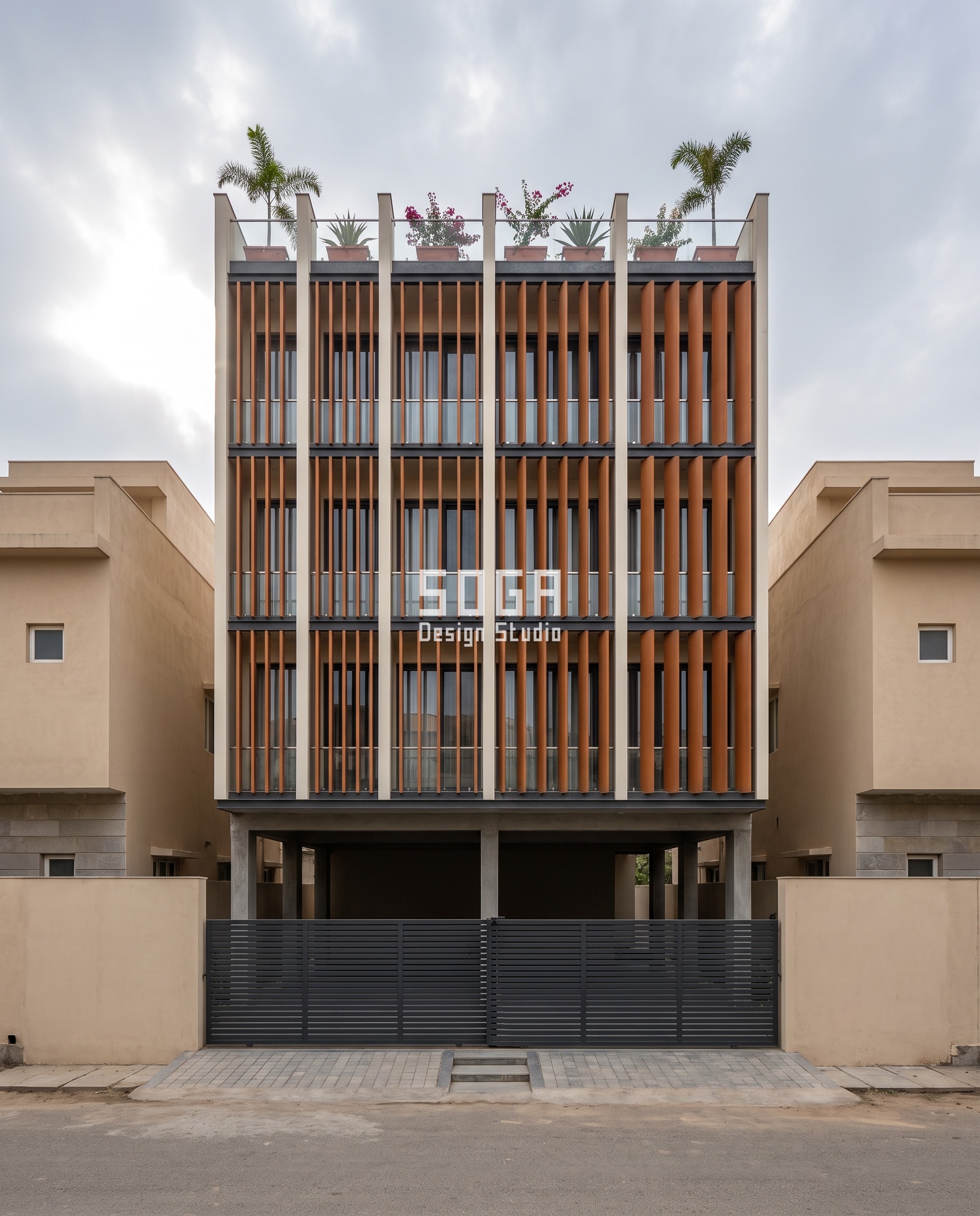
An 8.1 m frontage on a 9 m internal road in the Piprali Road plotted extension, G+3, 3 m setbacks. The house elevation behind it is ordinary and uneven: living-room sills at 500 mm, bedroom sills at 800 mm, a kitchen window at 1100 mm, a toilet ventilator at 1950 mm, and a landing window at 1575 mm that belongs to neither floor. The screen ignores all five. A 1.0 mm pigmented titanium-zinc member runs at 250 mm centres, floor to floor, and the only thing that changes across the face is how far it stands off the wall: 180, 250, 450, 650 and 900 mm in five countable steps, closing the wall behind at 44.2, 35.0, 21.3, 15.1 and 11.0 degrees off normal. What you read from the street is the returned cheek, the same 180 to 900 mm turned back in the same sheet, and the standoff behind it is physically a black slot – not a shadow.
| Specification | Parametric Cheek Standoff |
|---|---|
| Product | 1.0 mm pigmented titanium-zinc members at 250 mm centres, cheek-returned in the same sheet, on hot-dip galvanised 80 x 40 SHS bracket arms at 1200 mm centres off cast-in channel |
| Module | One pitch bay, full storey height – 32 members per floor across 8.1 m at 250 mm centres, 2850 mm clear |
| What varies | Standoff from the wall: 180 / 250 / 450 / 650 / 900 mm – closing at 44.2 / 35.0 / 21.3 / 15.1 / 11.0 degrees off normal |
| Head-on free area | 70.0 per cent open head-on (175 mm clear gap in a 250 mm pitch) |
| Indicative rate | Rs 2,400-4,000 per sq ft installed, pigmented titanium-zinc |
Parametric Gap Cell
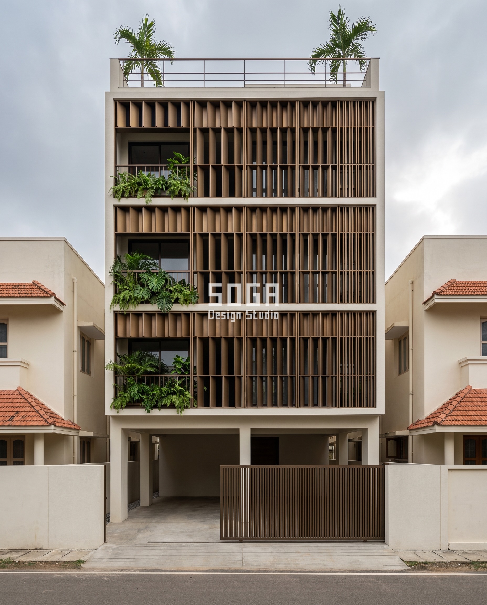
A 10.5 m frontage, G+3, in the Ramanputhur inland plotted colony on 9 m roads. Here the pitch and the standoff are both frozen – 600 mm grid, 420 mm off the wall – and the one quantity that moves is the clear gap between cells: 500, 420, 330, 230 and 120 mm, which is the same as saying the member face grows 100, 180, 270, 370 and 480 mm. The wall behind closes at 50.0, 45.0, 38.2, 28.7 and 15.9 degrees off normal. The rank tightens towards the stair core, where the landing window sits, and opens again over the living rooms where nothing needs hiding. Folded box cells in 1.5 mm bronze-PVD 444 ferritic stainless, seam-welded, with 8 mm open shadow-gap joints; the 420 mm return behind each cell is a real slot, not a painted one.
| Specification | Parametric Gap Cell |
|---|---|
| Product | 1.5 mm bronze-PVD 444 ferritic stainless folded box cells, 600 mm grid at 420 mm standoff, seam-welded and stitch-bolted to a 60 x 60 x 5 galvanised SHS ladder carrier, 8 mm open shadow-gap joints |
| Module | One 600 mm cell, full storey height – 17 cells per floor across 10.5 m |
| What varies | Clear gap at fixed 600 mm pitch and 420 mm standoff: 500 / 420 / 330 / 230 / 120 mm – closing at 50.0 / 45.0 / 38.2 / 28.7 / 15.9 degrees off normal |
| Head-on free area | 83.3 down to 20.0 per cent open head-on (500 mm to 120 mm clear in a 600 mm pitch) |
| Indicative rate | Rs 3,100-5,100 per sq ft installed, bronze-PVD 444 stainless |
Parametric Width Rank
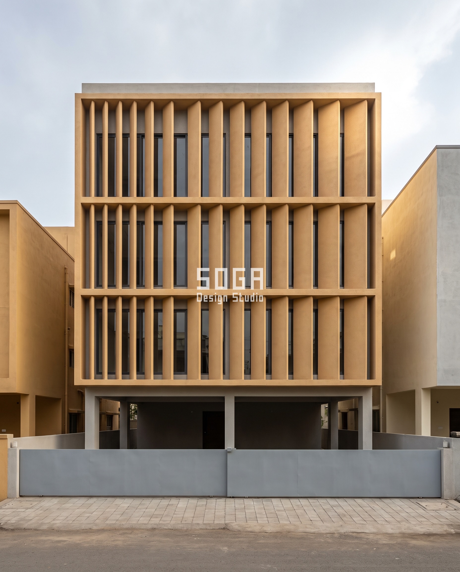
An 8.4 m frontage, G+3, on the Jamner Road plotted extension – a 9 m road and Tapi-valley dust. Pitch stays at 420 mm and the standoff stays at 360 mm, so the module count never changes and the carrier never moves. What varies is the member face width: 90, 150, 210, 275 and 340 mm, taking the clear gap from 330 mm down to 80 mm and the wall behind from 42.5 degrees to 12.5 degrees off normal. This is the cheapest of the five to build because nothing structural changes between the open state and the closed one – the bracket, the spine and the fixing are identical, and only the casting mould changes. Through-coloured ochre-buff pigmented polymer concrete, 18 mm shell, fine grit-blasted, on galvanised RHS spines.
| Specification | Parametric Width Rank |
|---|---|
| Product | 18 mm through-coloured pigmented polymer-concrete member shells on 100 x 50 x 4 galvanised RHS spines at 420 mm centres, stainless cleat-and-bolt at every floor rail |
| Module | One 420 mm pitch bay, full storey height – 20 members per floor across 8.4 m |
| What varies | Member face width at fixed 420 mm pitch and 360 mm standoff: 90 / 150 / 210 / 275 / 340 mm – closing at 42.5 / 36.9 / 30.3 / 21.9 / 12.5 degrees off normal |
| Head-on free area | 78.6 down to 19.0 per cent open head-on (330 mm to 80 mm clear in a 420 mm pitch) |
| Indicative rate | Rs 1,700-3,400 per sq ft installed, pigmented polymer concrete |
Parametric Bay Drift
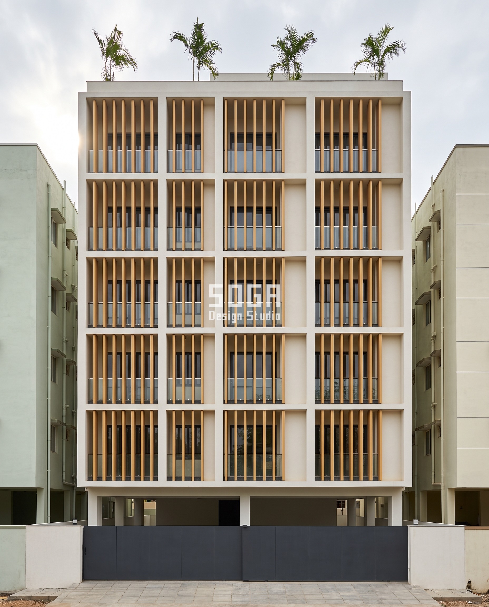
A 12.0 m frontage, G+5, on a 12 m road in the Sanjeevanagar plotted extension. This is the keystone of the argument, and it is a concept built to prove one number. The member is 160 mm wide at 480 mm centres on 640 mm outrigger arms, and the quantity that varies is the module phase against the 3000 mm structural bay: 0, 120, 240 and 360 mm, which is 0, 25, 50 and 75 per cent of the pitch. Six and a quarter modules land in every structural bay, so the grid drifts visibly against the frame from one bay to the next. The closing angle is 26.6 degrees in all four bays. Identical. The rank slides against the structure and the angle does not care, which is the entire thesis of this house elevation stated as a single number. The 300 mm plastered pilaster cheek is what lets you measure the offset from the street.
| Specification | Parametric Bay Drift |
|---|---|
| Product | Pultruded GFRP 160 x 60 x 6 member sections at 480 mm centres on 640 mm galvanised steel outrigger arms, through-pigmented sand-amber UV-stable veil, stainless through-bolt at every storey rail |
| Module | One 480 mm pitch bay, full storey height – 25 members per floor across 12.0 m, 6.25 modules to every 3000 mm structural bay |
| What varies | Module phase offset against the 3000 mm structural bay: 0 / 120 / 240 / 360 mm (0 / 25 / 50 / 75 per cent of pitch) – closing at 26.6 degrees in all four bays |
| Head-on free area | 66.7 per cent open head-on, identical in all four bays (320 mm clear in a 480 mm pitch) |
| Indicative rate | Rs 1,700-3,400 per sq ft installed, pultruded GFRP |
Parametric Splay Reveal
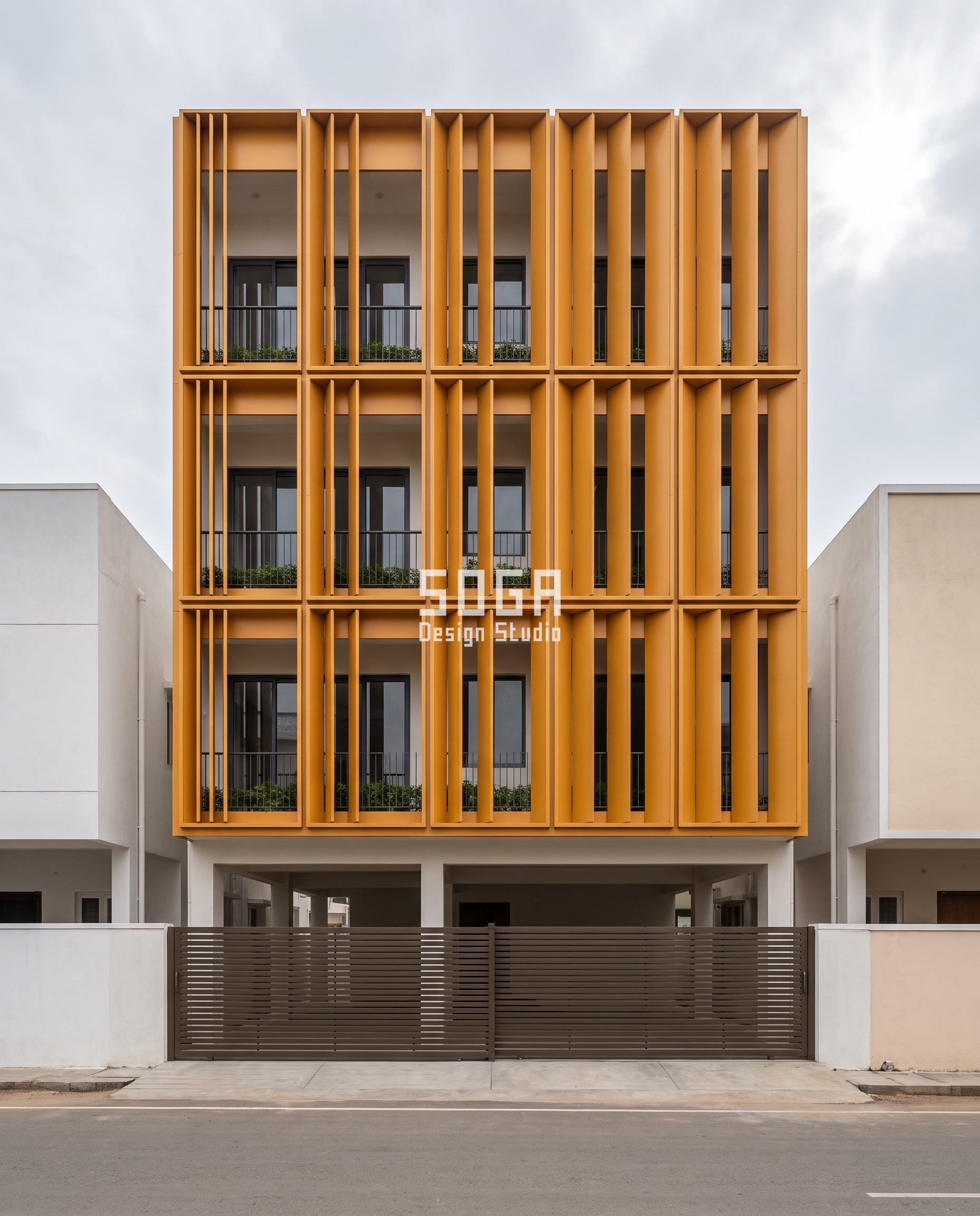
A 9.6 m frontage, G+3, in the Ballepalli plotted colony on a 9 m road. The outer cassette frame is one dead-flat plane across the whole house elevation and nothing ever steps forward of it. What moves is how far back inside each cassette the member rank sits: a reveal set-back of 60, 140, 240, 340 and 450 mm at a fixed 200 mm internal pitch on 60 mm members, closing the wall behind at 66.8, 45.0, 30.3, 22.4 and 17.3 degrees off normal. The collar cheeks are splayed 20 degrees, so read flat-on they measure 22, 51, 87, 124 and 164 mm – which is how the street sees the set-back at all. Super-durable polyester powder coat in warm marigold-amber, 30 per cent sheen, applied after fabrication to the 6063-T6 extruded sections.
| Specification | Parametric Splay Reveal |
|---|---|
| Product | 6063-T6 extruded frame-and-collar cassettes on a 600 mm grid, 20 degree splayed cheeks, internal 60 x 40 member rank at 200 mm centres, super-durable polyester powder-coated after fabrication, clip-fixed to a galvanised top-hat carrier |
| Module | One 600 mm cassette – 16 cassettes per floor across 9.6 m, 48 internal members at 200 mm centres |
| What varies | Reveal set-back within the cassette: 60 / 140 / 240 / 340 / 450 mm at fixed 200 mm pitch and 60 mm members – closing at 66.8 / 45.0 / 30.3 / 22.4 / 17.3 degrees off normal |
| Head-on free area | 70.0 per cent open head-on within each cassette (140 mm clear in a 200 mm pitch) |
| Indicative rate | Rs 1,700-3,400 per sq ft installed, powder-coated 6063-T6 aluminium |
How The Screen Is Fixed To An RCC Frame Without Touching The Brick
The load goes to the slab edge and nowhere else. That single sentence decides the whole substructure, and it is where most retrofit screens on Indian houses are got wrong. A 150 mm or 230 mm burnt-clay brick infill panel in an RCC frame is non-structural: a chemical anchor into a perforated or under-burnt brick develops maybe 1.5 to 3 kN in shear on a good day, and it fails by the brick face spalling away with the anchor still buried in it. The 650 mm bracket case resolves to about 9.35 kN per bolt pair across a 200 mm base plate. That arithmetic does not survive contact with brick. So every bracket lands on the slab edge, the vertical carrier spans floor to floor between two slab-edge fixings, and nothing touches the infill at any point. Where a bay has no slab at the level the panel wants one – the stair landing, precisely – the carrier simply runs past, picked up at the slabs above and below, and the landing panel hangs off that vertical. The table and the two details below carry the sections and the embedments.
| Design parameter | Specification |
|---|---|
| Member pitch | 250 mm on the reference concept; 200, 420, 480 and 600 mm on the other four |
| Member face width | 75 mm on the reference concept; 60 to 480 mm across the five |
| Standoff from the wall face | 180 to 900 mm; 250 to 450 mm covers a 9 m road with a 3 m setback |
| Clear storey run | 2850 mm clear floor to floor on a 3000 mm structural floor height |
| Bracket arm | Hot-dip galvanised 80 x 40 x 4 SHS at 1500 mm centres to 250 mm standoff; 100 x 50 x 5 SHS at 1200 mm centres at 650 mm standoff |
| Cantilever moment per bracket | 0.72 kNm at 250 mm standoff; 1.87 kNm at 650 mm – a 2.6x increase for the same skin |
| Anchorage | 100 x 10 mm hot-dip galvanised MS plate on 41 x 41 cast-in channel at every slab edge; on an existing frame, 2 no. M12 chemical anchors at 120 mm centres, 90 mm embedment, 75 mm minimum edge distance, into the 125-150 mm slab edge only |
| Vertical carrier | 60 x 60 x 5 galvanised SHS ladder spanning floor to floor between two slab-edge fixings; members bolt to it on stainless M8 cleats |
| Thermal movement | 10 mm slotted holes every 6 m of run, fixed point at mid-run. A 6 m powder-coated 6063-T6 extrusion moves 6.3 mm over a 45 K surface swing; the galvanised carrier under it moves 3.2 mm |
| Wind design | IS 875 Part 3; basic wind speed 39-47 m/s across the five districts, 1.0-1.5 kPa at 12-18 m above ground, about 0.8 kPa net on a 30 per cent solid screen |
| Top of the standoff | 1.5 mm capping flashed 75 mm into the wall, 1:12 fall outwards, turned 5 degrees clear of the face, 15 mm drip lip |
| Bottom of the standoff | Left completely open – no bottom rail, no closing angle, 25 mm clear above the plinth so nothing can dam |
The two details that decide whether it survives
- ANCHORAGE – the load goes to the slab edge and nowhere else. The 650 mm bracket case resolves to about 9.35 kN per bolt pair across a 200 mm base plate, and a chemical anchor in a 150 mm or 230 mm burnt-clay infill develops 1.5 to 3 kN in shear on a good day, failing by the brick face spalling away with the anchor still in it. So the fixing is a 100 x 10 mm hot-dip galvanised MS plate on a 41 x 41 cast-in channel at every slab edge, or on an existing frame 2 no. M12 chemical anchors at 120 mm centres, 90 mm embedment, 75 mm minimum edge distance, into the 125-150 mm slab edge only. The vertical carrier spans floor to floor between those two fixings. Where a bay has no slab at the level the panel wants it – the stair landing again – the carrier runs past and the landing panel hangs off it. Slotted holes every 6 m of run with the fixed point at mid-run: a 6 m length of powder-coated 6063-T6 aluminium extrusion moves 6.3 mm through a 45 K surface swing while the galvanised steel carrier under it moves 3.2 mm, so the slot is 10 mm.
- WATER, AND WHAT THE SECOND MONSOON DOES. A stood-off screen takes rain off the plaster and then puts it back down in one line. In year one this looks like a success. By the second monsoon the wall behind carries a dark tide line at exactly the level where the runoff lands, and if there is a horizontal member at the bottom of the standoff it is holding a 6 to 8 mm water film year round with the galvanising going at the weld. Three fixes, all of them small. Close the TOP of the standoff with a 1.5 mm capping flashed 75 mm into the wall, set to a 1:12 fall outwards and turned 5 degrees clear of the face with a 15 mm drip lip, so a squall is thrown off instead of running in behind. Leave the BOTTOM completely open – no bottom rail, no closing angle, a 25 mm clear gap above the plinth so nothing can dam. And give every member a 10 mm drip groove or a folded 8 mm return on the underside of its lower edge, so water breaks there rather than tracking back along the soffit to the wall. The wall behind still gets the full external-grade finish it would have had with no screen at all. This is a rainscreen, not a raincoat, and pricing it as a raincoat is how the plaster fails on schedule.
The Honest Limit: Three Places This Does Not Work
First, at the gate. Every visitor walks up and stands 1.5 to 3 m out, dead normal to the face, and at zero degrees off normal a screen is simply transparent. The uneven windows are completely visible to the one person you most wanted this to work on. The honest response is not to fix that. It is to accept that the screen is for the street and not for the doorstep, and to detail the entrance bay as a solid panel. Second, looking up. At 12 m out with a parapet at 12.6 m the vertical angle to the top floor is 42.5 degrees, and a screen made of vertical members closes horizontally and does nothing at all vertically, so the top floor’s sill mismatch stays readable from close in. Buying that back needs horizontal members, which then shade the rooms differently and start a different argument. Third, where there is nothing to stand off into: a zero front margin, or a municipal front-margin allowance already spent on a balcony, and a 250 to 450 mm standoff is not legal before it is discussed. And the plainest limit of all – this costs Rs 1,700 to 5,100 per sq ft to absorb a problem that was free to avoid while the lintel band was still on paper. If the drawing is not yet issued, close this page and hold the 2100 mm datum. This argument is for the building that is already standing.
What An Uneven-Window Elevation Screen Costs In India (2026)
Cost rises with bracket steel and standoff, not with skin area. Two screens of identical face area, one at 250 mm standoff and one at 650 mm, differ by roughly Rs 170 to 270 per sq ft in substructure alone, because the cantilever moment goes from 0.72 to 1.87 kNm and both the section and the bracket spacing have to move for it. That is what you are paying for. These are India 2026 market build cost bands, indicative and itemised per project. Lead time on a G+3 frontage of this size is typically 7 to 11 weeks from approved shop drawings to handover, with 3 to 5 of those weeks in fabrication.
| System / material | Indicative rate (per sq ft) |
|---|---|
| Pigmented titanium-zinc members, 1.0 mm, skin only | Rs 1,900-2,800 per sq ft |
| Bronze-PVD 444 ferritic stainless folded box cells, 1.5 mm, skin only | Rs 2,600-3,900 per sq ft |
| Pigmented polymer-concrete shells, 18 mm, skin only | Rs 1,250-1,900 per sq ft |
| Pultruded GFRP sections, through-pigmented, skin only | Rs 1,150-1,750 per sq ft |
| Super-durable powder-coated 6063-T6 aluminium cassettes, skin only | Rs 1,400-2,200 per sq ft |
| Hot-dip galvanised steel substructure at 250 mm standoff | Rs 260-430 per sq ft |
| Hot-dip galvanised steel substructure at 650 mm standoff | Rs 430-700 per sq ft |
| Cast-in channel or M12 chemical anchors, cleats, stainless fixings | Rs 90-160 per sq ft |
| Site fixing, access and scaffold | Rs 180-320 per sq ft |
| INSTALLED TOTAL – GFRP, polymer concrete or powder-coated 6063-T6 aluminium | Rs 1,700-3,400 per sq ft |
| INSTALLED TOTAL – pigmented titanium-zinc | Rs 2,400-4,000 per sq ft |
| INSTALLED TOTAL – bronze-PVD 444 stainless | Rs 3,100-5,100 per sq ft |
| Per-floor module count at these rates | 32 members per floor at 8.1 m / 250 mm pitch; 17 cells at 10.5 m / 600 mm; 20 members at 8.4 m / 420 mm; 25 members at 12.0 m / 480 mm; 16 cassettes and 48 internal members at 9.6 m / 600 mm grid |
| Note | India 2026 market build cost bands, indicative and itemised per project. Cost rises with bracket steel and standoff, not with skin area – the standoff is what you are paying for. |
Does The 25 To 35 Per Cent Fenestration Ratio Still Apply Behind A Screen?
Yes, unchanged. The fenestration ratio is a property of the wall, not of the screen, and a screen is not glazing, so it never enters the calculation.
What changes is that the ratio stops being the thing the street reads. Two numbers now live on one face and they must stay separate on the drawing. The wall’s solid-to-void ratio – 25 to 35 per cent glass on an Indian street face – is a daylight and heat number. The screen’s open-area ratio – 70.0 per cent head-on at 250 mm pitch with 75 mm members – is a sight-line number. Merge the two and the shading calculation goes wrong in both directions.
One consequence worth pricing in: a screen at 250 mm standoff cuts measured daylight at the window by roughly 15 to 25 per cent depending on the closing angle chosen. A street face already sitting at the 25 per cent end of the fenestration band should not also be closed to 35 degrees. Either open the gap or accept artificial light in the day.
The Alignment Hierarchy: Head Line First, Then Mullion, Then Sill
Every ranking page on this query gives the same order, and the order is correct. Heads first, then mullions, then sills. It is worth stating exactly why, because the reason also tells you when it expires.
Heads come first because the lintel band is being poured at 2100 mm anyway, so holding every opening head to it costs nothing and buys the strongest single line on the face. Mullions come second because a vertical is cheap to slide while the plan is on paper – moving a window 300 mm sideways inside a room usually costs nothing at all. Sills come last because they are ergonomic and will not move for any reason: 450 to 600 mm in a living room, 750 to 900 mm in a bedroom, 1050 to 1200 mm in a kitchen, above 1800 mm for a toilet ventilator.
So the hierarchy is a ranking of which disagreement you are willing to see, and it removes none of them. Head alignment expires the week the lintel is cast. Mullion alignment expires the day the plan is signed. Sill alignment was never available at all. What is still available on a house already standing is the angle at which all three stop being legible.
Which Openings An Indian House Elevation Actually Has
Five, typically, and only two of them are the window most people picture. A constant grid has to absorb all five, so it is worth listing them with their real sizes before choosing a pitch.
The two that matter to the screen are at the extremes: the toilet ventilator, whose head sits above the 2100 mm lintel band, and the stair-landing window, which sits at half-level and belongs to neither storey. Those two set the clear run the grid has to cover. Everything between them is easy.
| Opening on an Indian house elevation | Typical size, sill and head |
|---|---|
| Bedroom or living-room window | 1200 x 1500 mm; sill 450-900 mm; head on the 2100 mm lintel band |
| Kitchen window over the counter | 900 x 1050 mm; sill 1050-1200 mm; head on the 2100 mm lintel band |
| Toilet ventilator | 600 x 450 mm; sill above 1800 mm; head at about 2250 mm, which is above the lintel band and needs its own small lintel or sits in the slab band |
| Stair-landing window | 900 x 1200 mm; sill about 1575 mm above the floor below on a 3000 mm floor-to-floor; head at about 2775 mm – 675 mm above the band below it and 225 mm under the slab soffit above |
| Balcony or utility door | 900 x 2100 mm; head on the lintel band; no sill at all |
| Clear run the grid has to cover | 2850-3000 mm per storey, floor to floor |
Why One Constant Grid Replaces The Elevation Instead Of Decorating It
Because a pattern sits on an elevation and leaves the elevation in charge, while a datum takes charge instead. That is not a figure of speech – it is a statement about which quantities are still unspent.
Opening size belongs to the room, pitch to the 3000 mm structural bay, set-out to both. All three were spent before the front elevation was drawn, which is why every page that tries to compose with them arrives at a hierarchy rather than a fix. Once the grid is the datum, the only decision left is one angle in degrees.
The Chittoor concept above was drawn as the proof. Four bays, four phase offsets against the 3000 mm structural bay – 0, 120, 240 and 360 mm – and the closing angle is 26.6 degrees in every one of them. The rank slides visibly against the frame and the angle does not move at all. If the grid were a pattern that had to agree with the structure, that drift would be a defect. As a datum it is simply information about the frame, and the thing it was hired to hide stays hidden at the same 26.6 degrees throughout. How large that module should be for the height it is read at is a separate calculation, set out in facade module size against building height and viewing distance.
Misalignment Means Something Else On Site – And This Is Not It
On a fabrication drawing, misalignment means setting-out tolerance: panel to panel, plus or minus 2 to 3 mm on a 600 mm cassette grid, accumulating along a 9.6 m run until a joint visibly steps. That is a different problem with a different cure – datum strings, install sequence, adjustable cleats – and we wrote it up on its own in facade installation sequencing and tolerance in India.
This post is not about that. Here the openings are not wrong; they are correct and they disagree. Nothing on site is out of tolerance, nothing needs shimming, and no fabricator caused it. Use the test: if the joints in your screen step and the windows behind it are fine, you have the tolerance problem. If the joints are perfect and the windows behind are at five different heights, you have this one. The two get confused constantly, and the cures do not transfer in either direction.
Privacy, Module Size And Front Margin: Three Questions This Does Not Answer
Three adjacent questions come up every time this one does, and this post deliberately leaves all three alone because each needs its own geometry.
Whether the screen blocks the view out from inside is a different calculation entirely. The angle here is measured from outside looking in, and the inside-out case is asymmetric in section because the eye sits close to the glass rather than 12 m away. That is worked through in does a facade screen block the view from inside. How large the module should be for the height of the building and the distance it is read from is set out in facade module size by building height. And how much standoff the front margin will legally allow – the thing that actually decides whether you get 250 mm or 900 mm – is in facade projection in the front setback.
For the wider system logic behind all five concepts, and the material and cost bands they sit in, start at parametric facade design in India and the SOGA parametric systems line.
Related Reading
- Parametric facade design in India: systems, materials and cost
- SOGA parametric systems – the facade product line
- Facade projection in the front setback: how much standoff is legal
- Does a facade screen block the view from inside?
- Facade module size by building height and viewing distance
- Facade installation sequencing and tolerance in India
- Vertical fins vs horizontal louvers: one member, two axes
Frequently Asked Questions
Can uneven windows on a house elevation be fixed without moving them?
Yes. Stop trying to align them and put one constant grid in front instead – same member, same pitch, same set-out on every floor. At a 250 mm pitch with 75 mm members standing 250 mm off the wall, the openings behind are hidden beyond 35.0 degrees off normal, and beyond 21.3 degrees at a 450 mm standoff. Nothing is cut and no opening moves.
How much does a screen over uneven windows cost in India?
Rs 1,700 to 3,400 per sq ft installed in pultruded GFRP, pigmented polymer concrete or powder-coated 6063-T6 aluminium; Rs 2,400 to 4,000 in pigmented titanium-zinc; Rs 3,100 to 5,100 in bronze-PVD 444 stainless. On an 8.1 m frontage at 250 mm pitch that is 32 members per floor. Cost rises with bracket steel and standoff, not with skin area.
Will a facade screen over uneven windows make the rooms dark?
It costs roughly 15 to 25 per cent of measured daylight at the window, depending on the closing angle. At a 250 mm pitch with 75 mm members the face is 70.0 per cent open head-on, so the loss is real but modest. A street face already at the 25 per cent end of the 25 to 35 per cent fenestration band should not also be closed to 35 degrees.
Does the front margin allow a screen to stand off the wall?
That depends entirely on the local bye-law and it must be checked before the standoff is fixed. The five concepts here range from 180 mm to 900 mm of standoff, and a 9 m road with a 3 m setback needs about 375 mm to close at 25 degrees. Where the front-margin allowance is already spent on a balcony, there may be nothing left to build into.
What does a stood-off screen do to the wall behind in the monsoon, and how often is it cleaned?
By the second monsoon an unflashed screen leaves a dark tide line where the runoff lands. Cap the top with 1.5 mm flashing turned 75 mm into the wall at a 1:12 fall, leave the bottom fully open with a 25 mm clear gap above the plinth, and give every member a 10 mm drip groove. Wash the standoff twice a year in dusty districts, once a year elsewhere.
Send Us The Elevation You Already Have
A photograph of the front and a plan with the sill heights marked is enough to start. We compute the closing angle your road width actually needs, and the standoff that buys it, before anyone talks about material. SOGA Design Studio works on facade design, parametric architecture, facade consultancy and metal facade fabrication across India. Drawings are issued to you under licence for the project they were made for.