A facade panel comes off a house in a squall, and the panel is almost always fine. The bracket behind it is not. Facade panel wind load is the pressure, in kilopascals, that wind exerts on a cladding panel or fin — pushing on the windward face, pulling outward at the leeward face and hardest of all at the corners. In India it is calculated under IS 875 (Part 3):2015 as Pz = 0.6 x Vz², and it is carried by the fixings, not by the panel. A facade panel on an Indian house is designed for roughly 0.8 to 1.5 kPa over most of its area, rising to 2.5 to 3.1 kPa inside the corner strip. Which is where the instinct goes wrong. When a panel worries us, we make it smaller. IS 875 charges us more for that, not less.
Where The Smaller-Panel Instinct Is Right
Half of it is right, and it is the half most fabricators have actually checked. Deflection under wind runs with the fourth power of the span, so halving the span of a panel at the same section cuts its wind deflection roughly sixteen-fold. The L/175 serviceability check that a small panel passes without argument is the only wind calculation performed on most Indian residential facade jobs. A 900 mm segment is also the largest piece two men can place off a scaffold on a 9.0 m frontage with no crane on the street. On serviceability, and on erection, smaller is genuinely better. The trouble is that deflection is a check on the panel and strength is a check on the fixing, and the two move in opposite directions. Facades do not tear in the middle of a panel. They come off at fixings, and shrinking the panel buys more fixings drilled into the same slab nose.
The Kutchi Bhunga Deletes The Corner Instead Of Designing For It
The bhunga (ભૂંગા) of Kachchh is a single-room circular house, 5 to 6 m in internal diameter — a low cylindrical mud-and-daub wall under a light conical thatch, built across the district for about two hundred years. A circle gives wind no flat face to press against and no corner for suction to gather at, so a bhunga has no Zone A at all. The load runs continuously around the wall as ring compression instead of collecting at four worst points, which is a large part of why bhungas were left standing around Bhuj in 2001. This is a load-path anchor, not a weather one. The bhunga is not doing anything clever about the sky; it deletes the single worst bracket. A rectangular house on a rectangular plot cannot do that, which is exactly why the rate has to do the work instead.
The Rule: Change The Rate, Move The Peak
Wind does not load a facade panel evenly and then stop. It loads the one bracket where the panel’s section stops changing. That distribution along the part is a design variable, and the cheapest way to control it is the rate — how many degrees of splay per 100 mm, how many millimetres of radius per metre, how many degrees of twist per metre the section changes as it runs. Change the rate and the peak reaction moves off the bracket that was going to fail. Nothing about the part gets bigger. Nothing about it gets smaller either, which is the point: the module, the depth and the opening stay exactly where the elevation drawing put them. On the Kakinada house the reveal lining runs out at 1.8 deg per 100 mm at the sheltered south-west end and 5.4 deg per 100 mm at the exposed north-east corner. The opening is 2100 x 2600 mm and the reveal depth is 450 mm at both ends and on every floor. A faster run-out turns a flat cantilevered lining into a shallow folded plate over the same 450 mm of depth. The fold stiffens the free edge, so the segment pushes its load sideways into the two flanking carriers instead of hanging off the bracket at mid-length.
What Actually Sets Facade Panel Wind Load On A House?
Four things set it. Only one of them is the city on the wind map, and it is not the strongest of the four. The other three are the plot’s own plan dimensions, the tributary area behind a single bracket, and the roughness of the 500 m of ground upwind of the site. Each is a lookup you can audit. None of them is a judgement call, and none of them changes when you change the panel.
| Driver | What it sets, and to what |
|---|---|
| Net suction gradient across the front elevation | 1.69 kPa in the field rising to 3.10 kPa inside the code’s edge strip — a 1.83x jump across one elevation. It sets the splay run-out rate of the reveal lining: 1.8 deg per 100 mm at the sheltered south-west end to 5.4 deg per 100 mm at the exposed north-east corner, with the opening at 2100 x 2600 mm and the reveal depth at 450 mm identically at both ends and on every floor. |
| The plot’s least horizontal dimension | A 9.0 m frontage on a 15 m deep plot sets the local-pressure edge strip at 0.25 x 9.0 = 2.25 m measured in from each corner, so 4.5 m of a 9.0 m frontage. Half the front elevation is edge strip. The strip is derived from the building’s plan, never from the cladding, and on a plot deeper than it is wide the two strips meet in the middle. There is no field zone left to move a panel into. |
| Tributary area behind one bracket | A 900 mm segment at 600 mm carrier centres is 0.54 sq m. That sets Ka, the area-averaging factor: 0.8 at 100 sq m or more, 0.9 at 25 sq m, 1.0 at 10 sq m or less. At 0.54 sq m the panel is pinned at 1.0, the worst value the code offers, and further shrinking earns no credit at all. |
| Upwind terrain roughness inside the fetch | It sets k2, the terrain-and-height factor from IS 875 Table 2, and through k2 it sets Vz and Pz. Mangaluru: Vb 39 m/s, Terrain Category 1 open coastal, k2 = 1.07 at 12 m, Pz 1.04 kPa. Jamshedpur: Vb 47 m/s, Terrain Category 3 built-up colony, k2 = 0.94 at 12.5 m, Pz 1.17 kPa. An 8 m/s gap in basic wind speed collapses to 0.13 kPa. Across the five houses the sequence runs Kakinada 1.41, Bareilly 1.33, Jamshedpur 1.17, Mangaluru 1.04, Solapur 0.86 kPa. |
When two drivers ask for opposite things, the rate wins and the bracket centres follow it — never the reverse. On the north-east corner reveal of the Kakinada house, at z = 15 m, the suction driver wants the fastest run-out, 5.4 deg per 100 mm, to fold the lining and push its load sideways. But that same panel sits inside the edge strip, where the carrier centres have already been tightened from 600 mm to 400 mm, and at 400 mm the flanking carriers are so close that the fold lands almost on top of one. The fold then does no structural work at all and only eats clear daylight from a 2100 mm opening that happens to be the corner bedroom’s window. So set the run-out first at the full 5.4 deg per 100 mm, then read the centres off the folded section and let them open back out to 500 mm in the corner bay. Do not do both. Doing both pays twice for one problem, and the extra carrier buys a second thermal bridge and a second anchor into the same slab nose for capacity you already had. The honest arithmetic behind that precedence is short. A field bracket carries 1.69 kPa over 0.9 x 0.6 m, which is 0.92 kN. A corner bracket after tightening to 400 mm carries 3.10 kPa over 0.9 x 0.4 m, which is 1.12 kN. The corner bracket is still 22 per cent worse than the field bracket after you have paid for the extra rails. Centres alone cannot catch a 1.83x jump in pressure. That is precisely the gap the rate is there to close.
Five SOGA Concepts, One Rate Varied On Each
All five are SOGA concepts, designed and priced as a set for this argument. None is built, commissioned or under construction — the engineering is the credibility here, not a photograph of a finished job. Each one is a controlled experiment on a single building: every dimension held constant, exactly one rate varied along the run. They are sequenced by design pressure at the panel, highest first, so you can find your own city between two of ours and interpolate. Kakinada 1.41 kPa, Bareilly 1.33 kPa, Jamshedpur 1.17 kPa, Mangaluru 1.04 kPa, Solapur 0.86 kPa. The constants column carries the argument as hard as the variable does, so read both.
Parametric Splay Cone
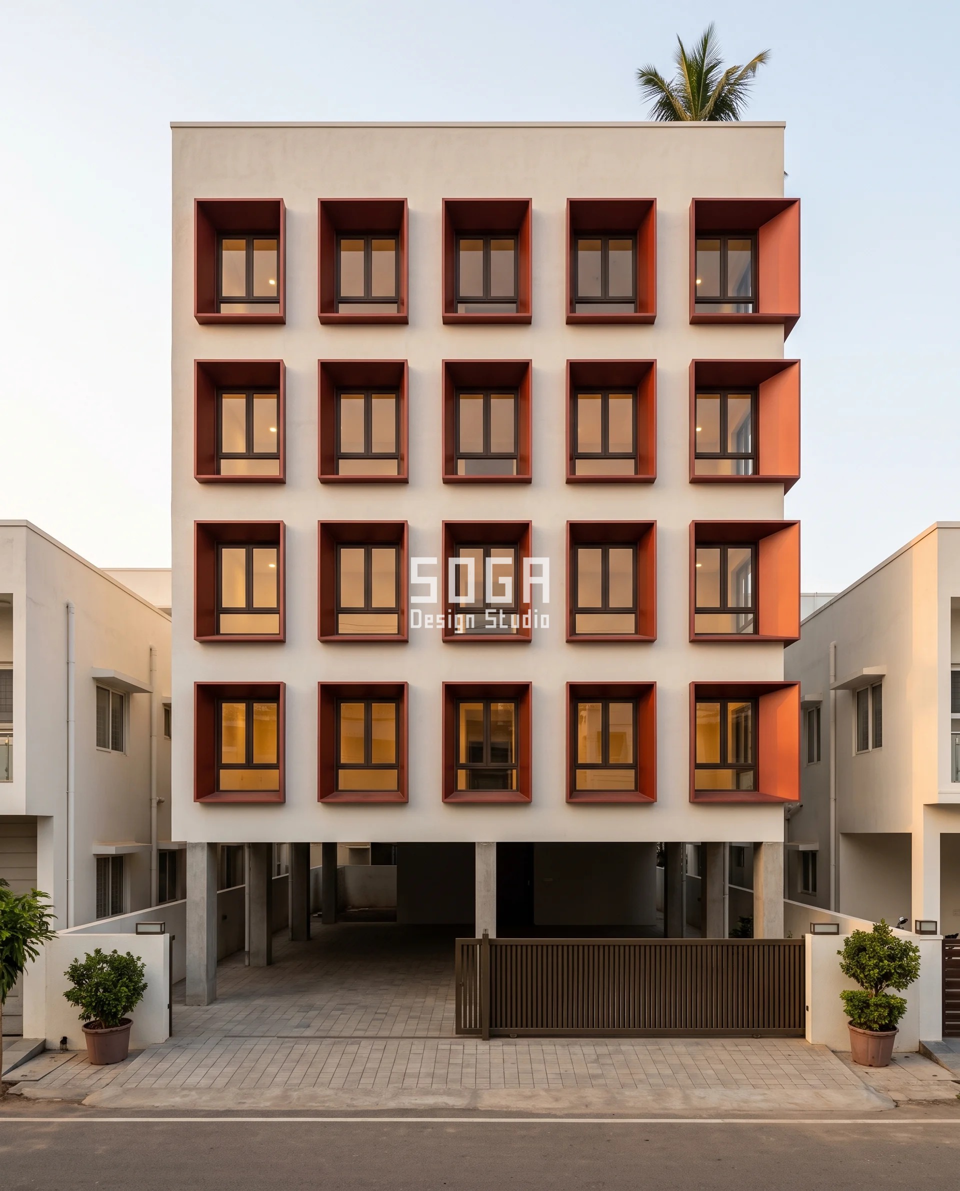
Parametric Splay Cone varies the run-out rate of a window reveal lining and nothing else. Every opening on this G+4 is 2100 x 2600 mm, every reveal is 450 mm deep, and the field cladding is identical from the stilt to the parapet. What changes is how fast the lining splays outward across those 450 mm: 1.8 deg per 100 mm at the sheltered south-west end, 5.4 deg per 100 mm at the exposed north-east corner. Kakinada sits on the Andhra coast, so the design pressure at z = 15 m is 1.41 kPa in the field and about 3.1 kPa of net suction inside the 2.25 m edge strip — the highest of the five. The faster run-out folds a flat cantilever into a shallow plate, and the plate pushes its reaction sideways into the flanking carriers rather than into the mid-length bracket. The elevation reads as a set of deepening sienna-red funnels. It is a bracket schedule that happens to be visible.
| Specification | Parametric Splay Cone |
|---|---|
| Product | 3 mm 5005-H14 marine-grade aluminium sheet, folded with 25 mm returns, Class II anodised 25 micron to IS 1868 grade AC25 in sienna red, blind-fixed to a 316 stainless serrated carrier with M10 A4-70 fixings |
| Module | 900 mm reveal-lining segment; carrier at 600 mm centres in the field and 400 to 500 mm inside the 2.25 m edge strip |
| What varies | Splay run-out rate — 1.8 deg per 100 mm to 5.4 deg per 100 mm. Design pressure Pz 1.41 kPa at z = 15 m |
| Indicative rate | ₹2,100–2,900 per sq ft |
Parametric Spiral Edge
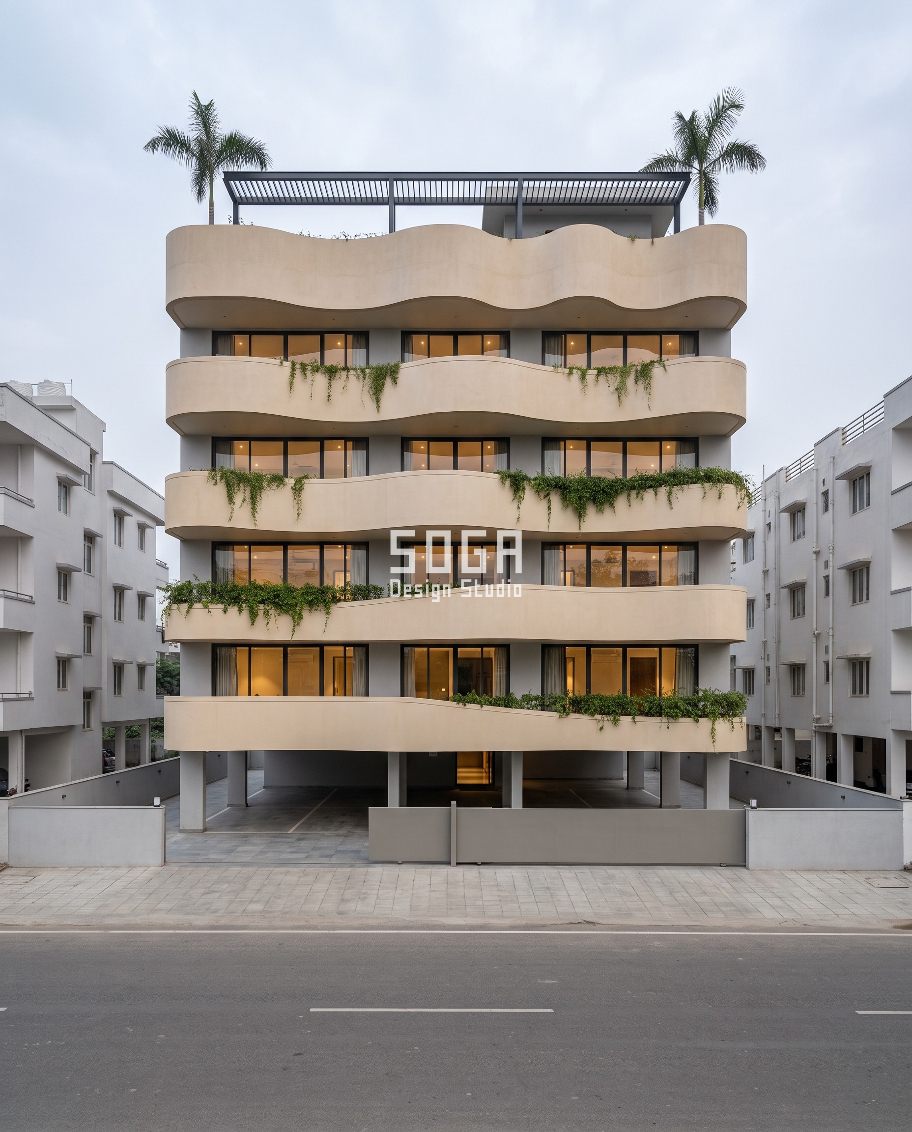
Parametric Spiral Edge varies how fast the front edge of a balcony band curves, floor by floor. The band projects 900 mm on every level, returns 500 mm, and is built from a 1200 mm ultra-high-performance concrete cassette that never changes size. The plan radius of the edge falls from 9000 mm at the first floor to 2200 mm at the fifth, which is a curvature rate running 810 mm per metre up to 2,190 mm per metre. Bareilly is a direct entry in the code’s city table at Vb 47 m/s, and at z = 19 m in a built-up colony the panel sees 1.33 kPa. Tighter curvature raises the shell’s own arching stiffness, so the outrigger reaction falls exactly where the band is most exposed, at the top two floors. Every cassette is single-curvature and developable, cast off one adjustable rail, so the curve tightens without the shell ever becoming a doubly curved part.
| Specification | Parametric Spiral Edge |
|---|---|
| Product | 45 mm pigmented UHPC shell at 120 MPa or better, GFRP mesh reinforcement, lightly acid-etched, 110 kg per sq m, on hot-dip galvanised steel outriggers to EN ISO 1461 |
| Module | 1200 mm cassette on a galvanised steel outrigger; band projection 900 mm and band return 500 mm constant on every floor |
| What varies | Curvature rate — 810 mm per m to 2,190 mm per m as the edge radius falls 9000 mm to 2200 mm. Design pressure Pz 1.33 kPa at z = 19 m |
| Indicative rate | ₹2,400–3,200 per sq ft |
Parametric Crown Hex
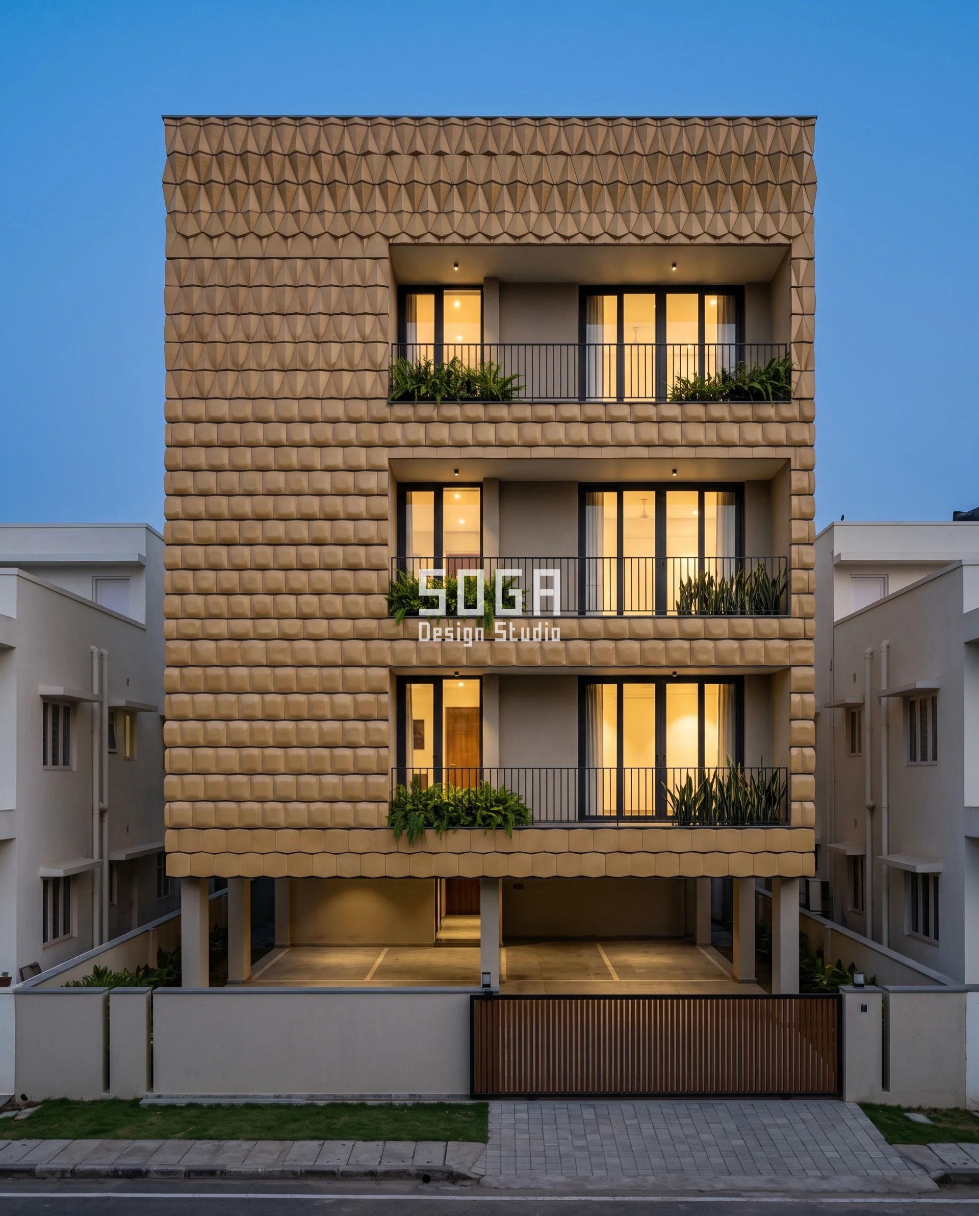
Parametric Crown Hex varies how sharply a ceramic shingle crowns and holds everything else dead still. Every tile is 300 mm across flats and 45 mm deep, laid dead level with an 8 mm open joint and zero tilt — footprint and depth identical on all of them. The crown fall-off runs 0.9 deg per 10 mm on the lower bands, a soft pillow, and 4.2 deg per 10 mm on the top two floors, a sharp cone. Jamshedpur is tabulated at Vb 47 m/s, the same basic wind speed as Bareilly, but Sonari is Terrain Category 3 and the panel sits at 12.5 m, so k2 is 0.94 and the design pressure lands at 1.17 kPa. A sharper crown stiffens the tile against its own clip, moving the peak clip force in from the tile edge toward its centre, where the substrate is continuous rather than interrupted by a joint.
| Specification | Parametric Crown Hex |
|---|---|
| Product | Pressed through-body ceramic shingle, wheat-gold glaze, blind clip on an aluminium T-rail over a hot-dip galvanised MS subframe, 8 mm drained open joint |
| Module | 300 mm across flats, 45 mm deep, 20 mm body, courses dead level, tilt 0 deg |
| What varies | Crown fall-off rate — 0.9 deg per 10 mm to 4.2 deg per 10 mm. Design pressure Pz 1.17 kPa at z = 12.5 m |
| Indicative rate | ₹1,500–2,100 per sq ft |
Parametric Taper Bough
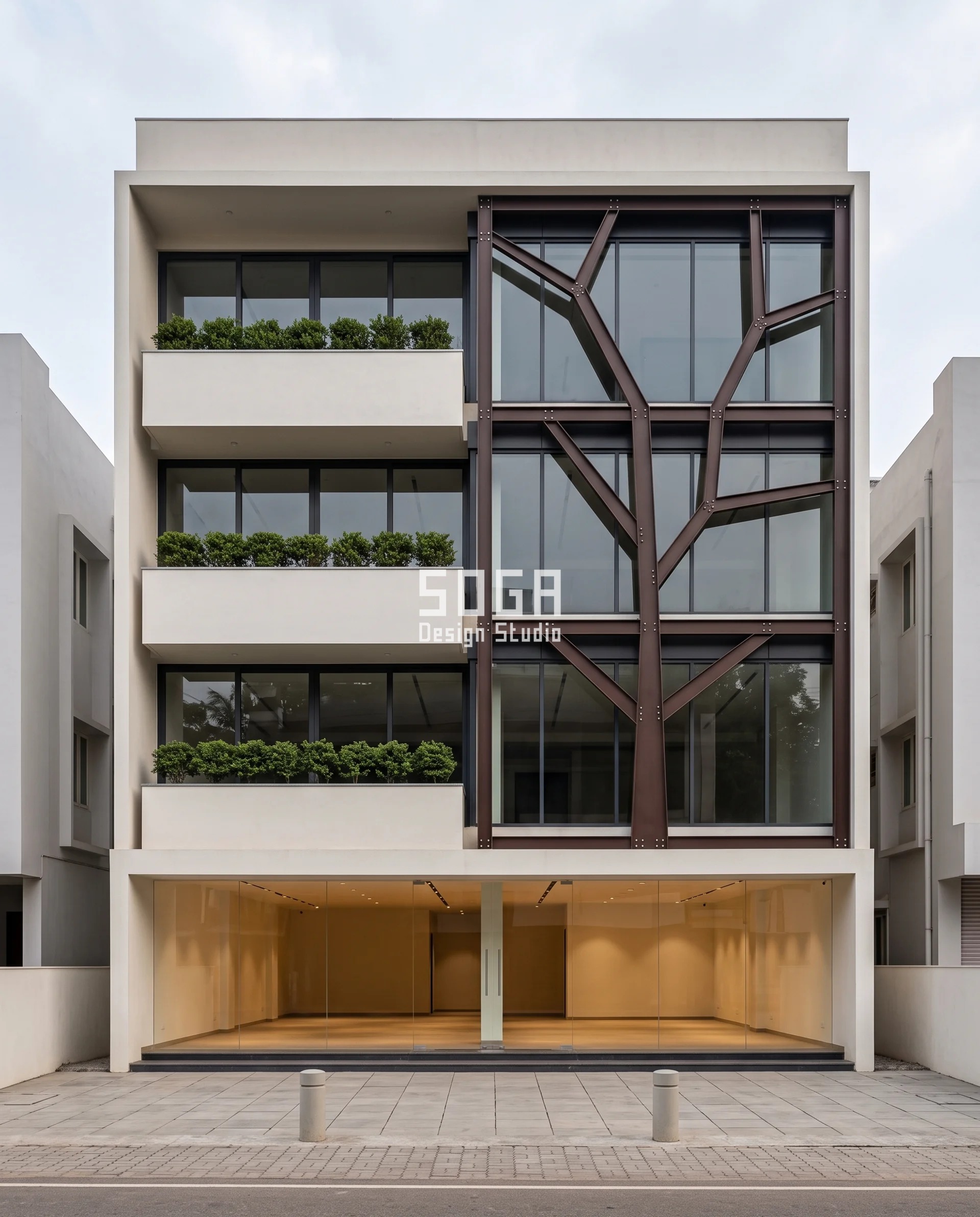
Parametric Taper Bough is the anomaly in the set, and it is the one worth reading twice. Mangaluru’s basic wind speed is 39 m/s against Jamshedpur’s 47, but Kadri’s frontage is open coastal ground, which is Terrain Category 1, where k2 is 1.07 at 12 m instead of 0.94. The design pressure lands at 1.04 kPa — within 0.13 kPa of a city carrying 8 m/s more wind on the national map. Looking up your city and stopping there is not a calculation. The frame itself is a branch structure standing 700 mm clear of the glazing on an 1800 mm node grid, every member cut from the same 16 mm plate, three branching generations and no more. The taper rate is what varies: 96 mm of width lost per metre in the first generation, 38 mm per metre in the second, 11 mm per metre in the third. Taper matches section to the moment diagram, so no node carries a step change in stiffness and the base fixing stops being the sole peak.
| Specification | Parametric Taper Bough |
|---|---|
| Product | 16 mm S355 laser-cut plate, hot-dip galvanised to EN ISO 1461 with a cocoa-brown polyester powder coat over the galvanising (duplex), M20 grade 8.8 bolts at expressed nodes, members designed to IS 800:2007 |
| Module | Laser-cut plate member on an 1800 mm node grid, 700 mm standoff from the glazing line, three branching generations |
| What varies | Taper rate — 96 mm per m, then 38 mm per m, then 11 mm per m across the three generations. Design pressure Pz 1.04 kPa at z = 12 m |
| Indicative rate | ₹2,800–3,800 per sq ft |
Parametric Helix Slat
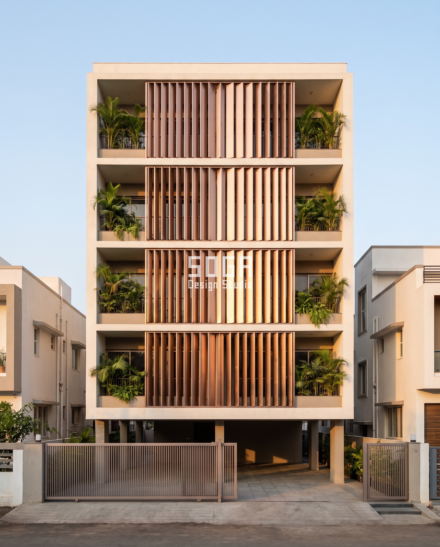
Parametric Helix Slat varies twist rate along a fin and holds the fin itself constant. Section 75 x 165 mm, centres 130 mm, slat length 3050 mm, wave amplitude 700 mm — every slat is the same part. The twist about the slat’s own vertical axis runs 0 deg per metre at the bay centre and 28 deg per metre at the bay ends, 85 degrees in total over the length of one slat. Solapur is not in the code’s city table; inland Maharashtra reads 39 m/s off the basic wind speed map, the same zone Pune, Nasik and Aurangabad are all tabulated in, which gives 0.86 kPa at z = 15 m and the lowest pressure of the five. Turning the blade edge-on at the bay ends drops its projected area into the wind at exactly the point where the end rail’s reaction was highest. The wave you see is the twist schedule, not a shape drawn first.
| Specification | Parametric Helix Slat |
|---|---|
| Product | 1.5 mm 316L stainless shell with a rose-gold PVD coating, helically formed on a 60 x 12 mm 304 stainless flat-bar spine, fixed top and bottom into band rails |
| Module | 75 x 165 mm slat section at 130 mm centres, 3050 mm long, 700 mm wave amplitude — every slat is the same part |
| What varies | Twist rate — 0 deg per m at bay centre to 28 deg per m at bay ends, 85 deg total over the slat. Design pressure Pz 0.86 kPa at z = 15 m |
| Indicative rate | ₹2,200–3,000 per sq ft |
How Is A Facade Panel Fixed To Take 3.1 kPa Of Suction?
By designing the anchor for suction plus dead weight pulling a cone of concrete out of the slab edge, and by giving that cone the edge distance it needs. The governing case is not bending in the panel. It is pull-out at the fixing: 1.12 kN per corner bracket against 0.92 kN in the field on the Kakinada concept. The carrier is a 316 stainless serrated channel, and the serration is the whole point — it lets the M10 A4-70 fixing land anywhere along the rail, so the change from 600 mm to 400 or 500 mm centres inside the edge strip is a site decision inside the standard plus-or-minus 25 mm three-dimensional anchor tolerance, not a redrawn shop drawing. The anchor into the RCC slab nose is a post-installed mechanical anchor at 80 mm effective embedment with 100 mm minimum edge distance, held clear of the IS 456:2000 cover zone.
| Design parameter | Specification |
|---|---|
| Governing code | IS 875 (Part 3):2015, within the framework of NBC 2016 Part 6 |
| Design wind speed | Vz = Vb x k1 x k2 x k3 x k4, in m/s |
| Design wind pressure | Pz = 0.6 x Vz², with Vz in m/s and Pz in N per sq m. 1 kPa = 1 kN per sq m = 1,000 N per sq m |
| Net panel pressure | Pz x Kd x Ka x Kc x (Cpe − Cpi) |
| Module | 900 mm reveal-lining segment, 3 mm 5005-H14 aluminium, folded with 25 mm returns |
| Carrier | 316 stainless serrated channel — 600 mm centres in the field, 400 to 500 mm inside the 2.25 m edge strip |
| Fixing | M10 A4-70 stainless, blind-fixed through the carrier |
| Anchor | Post-installed mechanical anchor into the RCC slab nose — 80 mm effective embedment, 100 mm minimum edge distance |
| Isolator | 10 mm polyamide pad under every bracket |
| Governing load case | Suction plus dead weight, concrete cone pull-out — 1.12 kN per corner bracket, 0.92 kN per field bracket |
| Movement | A 900 mm aluminium segment across a 45 K surface swing grows 0.94 mm; fixed runs of four with a movement joint every 3.6 m and a 6 mm slotted hole at the free end |
| Finish | Class II anodising, 25 micron, IS 1868 grade AC25 |
The two details that decide whether the bracket survives
- The concrete cone needs the edge distance far more than the bolt needs the diameter. Under suction the thing that fails at a slab nose is not the anchor. It is a cone of concrete pulled out around it. An anchor set 40 mm from the edge of a slab has a fraction of its catalogue capacity whatever the fixing schedule says, so the schedule specifies 100 mm minimum edge distance and 80 mm effective embedment, and the drawing keeps both clear of the IS 456:2000 cover zone. On a job with a shallow or badly compacted slab nose this is the line that gets redrawn first, and going from an M10 to an M12 does not help, because the failure was never in the steel.
- Movement is arithmetic, not habit. A 10 mm polyamide isolator sits under every bracket and does two jobs: it breaks the thermal path into the slab, and it keeps the 316 stainless carrier off the 5005 aluminium lining so the two metals are never in wet contact. A 900 mm aluminium segment across a 45 K surface swing grows 0.94 mm, so segments run in fixed lengths of four with a movement joint every 3.6 m and a 6 mm slotted hole at the free end to take the 3.7 mm of accumulated run. The fixed point of every run is the bracket nearest the corner, so the lining grows away from the edge strip rather than into it.
The Honest Limit: Where The Rate Stops Working
The rate lever runs out in two places, and neither is rescuable by drawing harder. The first is scale and plan form. This is a lever for buildings below roughly 100 m with a plan the code’s pressure-coefficient tables actually cover. On a genuinely curved or re-entrant plan, or on a tower, the corner coefficient stops being a table lookup and the project goes to a boundary-layer wind tunnel — common Indian practice on tall work, not a blanket code mandate. Nothing here is near that line; the tallest of these five is 19 m. The second limit is the one that actually bites. The rate cannot rescue a bad anchor. If the slab nose is under-strength, badly compacted, or the anchor lands inside its edge distance, the concrete cone comes out at a fraction of the calculated capacity, and no amount of splay run-out, taper or twist changes that. These five are SOGA concepts and they assume a sound IS 456:2000 substrate. On a real project the first thing bought is a site pull-out test. If the results come back low, the facade changes character entirely: it gets a continuous back-frame spanning slab to slab, the argument becomes one about stiffness rather than rate, and the cost band moves with it. That should be priced on day one, not discovered in month seven. One more concession, made plainly. We do not carry glazing performance here. Glass thickness, U-value and acoustic ratings belong to the curtain-wall lane; this post is about the panel, the fin and the bracket behind them.
What These Five Facades Cost To Build In India (2026)
Priced per square foot of facade face, itemised per project, and always as a range. The bands below cover material, substructure, fixings, finish and installation. They exclude scaffolding and access equipment, RCC remedial work at the slab nose, and any redesign triggered by a low site pull-out test. Two costs move independently of the material and neither appears on a cladding quotation: the corner zone, where carrier centres tighten and the bracket count rises across 2.25 m in from each corner, and the anchor, where a weak slab nose turns a bracket schedule into a back-frame. Both belong in the budget on day one.
| System / material | Indicative rate (per sq ft) |
|---|---|
| Parametric Splay Cone — 3 mm 5005-H14 anodised aluminium reveal lining on a 316 stainless serrated carrier, Kakinada | ₹2,100–2,900 per sq ft |
| Parametric Spiral Edge — 45 mm pigmented UHPC shell with GFRP mesh, on hot-dip galvanised steel outriggers, Bareilly | ₹2,400–3,200 per sq ft |
| Parametric Crown Hex — pressed through-body ceramic shingle on an aluminium T-rail over a galvanised MS subframe, Jamshedpur | ₹1,500–2,100 per sq ft |
| Parametric Taper Bough — 16 mm S355 laser-cut plate, duplex finish, bolted at expressed nodes, Mangaluru | ₹2,800–3,800 per sq ft |
| Parametric Helix Slat — 1.5 mm 316L PVD-coated shell on a 304 flat-bar spine, Solapur | ₹2,200–3,000 per sq ft |
| Corner-zone fixing premium — centres tightened from 600 mm to 400–500 mm across 2.25 m in from each corner | Bracket count rises 20 to 50 per cent inside the strip; it lands on the fixing line, not the cladding line |
| Site pull-out test on the RCC slab nose, before the facade is ordered | A small line item beside the facade — and if it comes back low, the system moves to a continuous back-frame and every band above moves with it |
What Is The Design Wind Pressure For A House Facade In India?
A house facade in India is designed for a wind pressure of roughly 0.8 to 1.5 kPa in the field, calculated under IS 875 (Part 3):2015. The chain is short. Read the basic wind speed Vb for the site in metres per second, multiply it by four factors to get the design wind speed Vz = Vb x k1 x k2 x k3 x k4, then take Pz = 0.6 x Vz² with Vz in m/s and Pz in newtons per square metre. One kilopascal is one kilonewton per square metre, or 1,000 N per sq m. Everything below stays in kPa.
Three of the five sites are direct entries in the code’s city list: Bareilly at 47 m/s, Jamshedpur at 47 m/s and Mangalore at 39 m/s. Kakinada and Solapur are not tabulated by name, so their basic wind speed is read off the basic wind speed map instead, and the table below says so in its own column. Kakinada reads 50 m/s — every listed city on that coastal band is 50, including Visakhapatnam, Vijayawada, Nellore and Chennai, and the Andhra Pradesh wind hazard map carries no 55 m/s zone anywhere in the state. Solapur reads 39 m/s, the inland Maharashtra zone that Pune, Nasik and Aurangabad are all tabulated in. Most pages on this subject quote the formula and never say where Vb came from.
The k2 column is what makes the table auditable rather than assertable. IS 875 Table 2 gives Terrain Category 1 as 1.05 at 10 m, 1.09 at 15 m and 1.12 at 20 m, and Terrain Category 3 as 0.91 at 10 m, 0.97 at 15 m and 1.01 at 20 m. Bareilly at 19 m, Jamshedpur at 12.5 m and Mangaluru at 12 m are interpolated between those values, which the table’s own note permits. Kakinada and Solapur at 15 m are read straight off it. Terrain Category 3 is the honest default for an Indian residential colony; Category 1 is open coastal ground with almost nothing upwind.
| City, building and basic wind speed Vb | Terrain, height, factors and design pressure Pz |
|---|---|
| Kakinada, Ramaraopeta — Parametric Splay Cone, G+4 residence. Vb 50 m/s (MAP — not tabulated in the code’s city list) | Terrain Category 3, z = 15.0 m. k1 1.00, k2 0.97, k3 1.00, k4 1.00 → Vz 48.5 m/s → Pz 1.41 kPa, with net suction to about 3.1 kPa inside the 2.25 m edge strip |
| Bareilly, Rajendra Nagar — Parametric Spiral Edge, G+5 residence. Vb 47 m/s (TABLE — listed in the code’s city table) | Terrain Category 3, z = 19.0 m. k1 1.00, k2 1.00, k3 1.00, k4 1.00 → Vz 47.0 m/s → Pz 1.33 kPa |
| Jamshedpur, Sonari — Parametric Crown Hex, G+3 residence. Vb 47 m/s (TABLE) | Terrain Category 3, z = 12.5 m. k1 1.00, k2 0.94, k3 1.00, k4 1.00 → Vz 44.2 m/s → Pz 1.17 kPa |
| Mangaluru, Kadri — Parametric Taper Bough, G+3 boutique showroom. Vb 39 m/s (TABLE — listed as Mangalore) | Terrain Category 1, open coastal, z = 12.0 m. k1 1.00, k2 1.07, k3 1.00, k4 1.00 → Vz 41.7 m/s → Pz 1.04 kPa — the lower basic wind speed, the higher terrain factor |
| Solapur, Hotgi Road — Parametric Helix Slat, G+4 residence. Vb 39 m/s (MAP — not tabulated; inland Maharashtra zone) | Terrain Category 3, z = 15.0 m. k1 1.00, k2 0.97, k3 1.00, k4 1.00 → Vz 37.8 m/s → Pz 0.86 kPa |
Does A Smaller Facade Panel Need Less Wind Resistance?
Making a facade panel smaller does not make it safer. IS 875 (Part 3):2015 applies an area-averaging factor Ka of 1.0 up to 10 square metres, 0.9 at 25 square metres and 0.8 at 100 square metres or more. A smaller panel is therefore designed for a higher pressure per square metre, not a lower one, because a gust peak is a local cell that never covers a large surface at one instant.
The 2015 revision made this explicit rather than implicit. Table 2 of the earlier edition carried size columns — the old Class A, B and C cladding classes — and the revision deleted them and put Ka in their place. The size penalty used to arrive as a quiet discount for being big. It now arrives as a named charge for being small.
The arithmetic on a real part is blunt. A 900 mm segment at 600 mm carrier centres has a tributary area of 0.54 sq m, which sits at Ka = 1.0, the worst value the code offers. Halving that segment to 450 mm takes the tributary area to 0.27 sq m and leaves Ka exactly where it was, while the number of anchors drilled into the same slab nose doubles. Taking a genuine 25 sq m zone down to 12.5 sq m moves Ka from 0.9 back toward 1.0 — about 11 per cent more design pressure per square metre, bought with twice the brackets.
The corner-zone pressure coefficient does not fall when the panel shrinks either, because it is set by the building’s plan dimensions and not by the cladding. So halving the panel leaves the pressure per square metre where it was, leaves the corner coefficient where it was, and doubles the fixings. That is the whole counter-intuitive result, and it is why the only lever left is the one that costs nothing: the rate at which the section changes along the part’s own length.
| Tributary area of the panel or zone | Ka, the IS 875 area-averaging factor |
|---|---|
| 10 sq m or less — every facade panel, fin, shingle and slat in this post | Ka = 1.00 — no averaging credit at all |
| 25 sq m — a large cassette zone or a long spandrel run | Ka = 0.90 — 10 per cent off the design pressure per sq m |
| 100 sq m or more — a whole facade zone or a structural bay | Ka = 0.80 — 20 per cent off the design pressure per sq m |
| 0.54 sq m — the Kakinada segment, 900 mm at 600 mm carrier centres | Ka = 1.00, and no further shrinking can improve it |
How Far Apart Should Facade Panel Brackets Be?
Facade panel brackets on a low-rise Indian house typically run at 600 mm centres in the field and tighten to 400 to 500 mm inside the code’s corner strip. On the Kakinada concept the carrier is a 316 stainless serrated channel at 600 mm centres across most of the elevation and 400 to 500 mm within 2.25 m of each corner, fixed with M10 A4-70 stainless into a post-installed mechanical anchor at 80 mm effective embedment.
Tightening centres does not close the corner gap on its own, and this is the number that makes the whole argument non-optional. A field bracket carries 1.69 kPa over a 0.9 x 0.6 m tributary area, which is 0.92 kN. A corner bracket after tightening to 400 mm carries 3.10 kPa over 0.9 x 0.4 m, which is 1.12 kN. After paying for the extra rails, the corner bracket is still 22 per cent worse than the field bracket. Centres cannot catch a 1.83x jump in pressure, which is why the section changes first and the centres are read off it afterwards.
Two different limits govern two different things, and they are easy to confuse on a small job. Deflection is serviceability: a panel or a mullion is commonly held to L/175 of its span, which on a 3.0 m member is about 17 mm, and it is a check on the part. Strength is ultimate: it is a check on the fixing, under suction plus dead weight. A fin or a slat that cantilevers, like the 3050 mm Solapur blade, is checked on tip deflection and on the moment at its two band rails rather than on a clear-span ratio. Passing L/175 tells you nothing at all about whether the anchor holds.
| Location on the elevation | Carrier centres and bracket reaction, Kakinada concept |
|---|---|
| Field — outside the 2.25 m edge strip | 600 mm centres, tributary 0.9 x 0.6 m, net 1.69 kPa → 0.92 kN per bracket |
| Edge strip — within 2.25 m of a corner, centres tightened | 400 mm centres, tributary 0.9 x 0.4 m, net 3.10 kPa → 1.12 kN per bracket, still 22 per cent worse than the field |
| Edge strip — after the splay run-out is raised to 5.4 deg per 100 mm | Centres open back out to 500 mm; the fold pushes the reaction sideways into the flanking carriers instead |
| Anchor into the RCC slab nose, every location | 80 mm effective embedment, 100 mm minimum edge distance, held clear of the IS 456:2000 cover zone |
| Fabrication tolerance | Serrated carrier takes the standard plus-or-minus 25 mm three-dimensional anchor tolerance, so a centres change is a site decision |
Is IS 875 Part 3 Applicable To A G+3 House?
Yes. IS 875 (Part 3):2015 governs wind loads on buildings and structures in India generally, and a G+3 or G+5 house is not exempt because it is small. Cladding on such a house is designed using local pressure coefficients on the edge and corner zones rather than the whole-building coefficients used for the frame, which is why a house facade panel can be designed for a higher pressure per square metre than the structure standing behind it.
k4, the importance factor for cyclonic regions, is where a knowledgeable reader will assume something has been forgotten. IS 875 sets k4 = 1.00 for ordinary structures, 1.15 for industrial structures and 1.30 for structures of post-cyclone importance. Kakinada is a cyclone-prone coastal location, so k4 is live there — but these are private houses, so 1.00 is correct and 1.41 kPa stands. A cyclone shelter on the same Kakinada street, with an identical facade on an identical geometry, would be designed for about 30 per cent more pressure.
That is the thesis restated from the other end. The pressure is handed to you by the code, by the site and by the building’s use. It is not negotiated down by shrinking the panel. What you actually control is where that pressure lands along the part, and the only free variable there is the rate at which the section changes as it runs.
Height matters only through k2, and on a house it matters less than the ground around it does. In Terrain Category 3, the default for an Indian residential colony, k2 runs 0.91 at 10 m, 0.97 at 15 m and 1.01 at 20 m. Going from a G+3 to a G+5 on the same plot moves the panel pressure by roughly 10 per cent. Moving that same G+3 from a built-up colony to open coastal ground moves it by nearly 15 per cent, in the wrong direction.
| Factor | Value used on these five houses, and why |
|---|---|
| k1 — risk and probability factor | 1.00 — 50-year mean probable design life on all five buildings |
| k3 — topography factor | 1.00 — upwind slope under 3 degrees on all five plots |
| k4 — cyclonic importance factor | 1.00 — private residences. 1.15 applies to industrial structures, 1.30 to structures of post-cyclone importance |
| Kd — wind directionality factor | 1.00 — local pressure coefficients are in use for cladding, so the 0.90 credit is not taken |
| Kc — combination factor | 1.00 — a cladding element is a single surface |
| Ka — area-averaging factor | 1.00 — tributary area 0.54 sq m, far below the 10 sq m threshold |
| Cpi — internal pressure coefficient | +0.5 — medium permeability, openings between 5 and 20 per cent of wall area, Clause 7.3.2 |
| Cpe — external pressure coefficient | −0.7 in the field, giving a net −1.2. −1.7 is the local edge-strip value used here, giving a net −2.2; reported ranges for wall edge zones run about −1.4 to −2.0, and every number downstream is traceable to the value used |
One caution the code cannot give you: passing the wind-load check does not make a panel quiet — a 47 m/s design gust sizes the bracket, but the complaint arrives at 12 m/s and is a frequency problem.
Related Reading
- Parametric facade design in India
- Parametric facade systems and what is actually buildable in India
- G+3 and G+4 house elevation design in India
- 3D parametric facade panels — design and cost in India
- How deep a facade projection should be
- Apartment building facade design and compliance for developers
- Commercial facade systems for offices, retail and IT parks
- Stilt parking house facade design in India
Frequently Asked Questions
How much wind load does a facade panel have to take in India?
Between roughly 0.8 and 1.5 kPa over most of a house facade, and 2.5 to 3.1 kPa inside the corner strip. On the five SOGA concepts in this post the design pressure at panel height runs from 0.86 kPa in Solapur to 1.41 kPa in Kakinada, calculated under IS 875 (Part 3):2015 as Pz = 0.6 x Vz². The corner figure, not the field figure, sizes the bracket.
Does a smaller facade panel need less wind resistance?
No. IS 875 (Part 3):2015 applies an area-averaging factor Ka of 1.0 up to 10 sq m, 0.9 at 25 sq m and 0.8 at 100 sq m or more, so a smaller panel is designed for a higher pressure per square metre, not a lower one. A 0.54 sq m facade panel is already pinned at Ka = 1.0. Halving it changes nothing except the number of anchors.
How far apart should facade panel brackets be?
On the Kakinada concept the carrier runs at 600 mm centres in the field and tightens to 400 to 500 mm inside the 2.25 m edge strip. Tightening alone does not close the gap: a field bracket takes 0.92 kN and a corner bracket at 400 mm centres still takes 1.12 kN, which is 22 per cent worse. Centres are set after the section, never instead of it.
Why is the corner of a building worse for facade wind load?
Because IS 875 (Part 3):2015 assigns higher local suction to an edge strip sized from the building’s own plan dimensions, not from the cladding. On a 9.0 m frontage that strip is 0.25 x 9.0 = 2.25 m in from each corner, so 4.5 m of a 9.0 m elevation is corner zone. Field pressure of 1.41 kPa rises to about 3.1 kPa inside it.
What does a wind-engineered facade panel system cost per sq ft in India?
The five systems here band from ₹1,500–2,100 per sq ft for the pressed ceramic crown up to ₹2,800–3,800 per sq ft for the 16 mm laser-cut steel branch frame, covering material, substructure, fixings, finish and installation. Scaffolding, RCC remedial work at the slab nose and any redesign after a low site pull-out test sit outside those bands.
Size The Bracket Before You Size The Panel
If your elevation is still a drawing, the rate costs nothing. Set the splay run-out, the curvature, the taper or the twist first, read the carrier centres off the resulting section, and the corner strip stops being the line item that wrecks the fixing schedule. If the elevation is already fabricated, the order is a site pull-out test, then a bracket schedule that respects edge distance, then whatever the test allows. SOGA Design Studio designs and details parametric facades across India — concept, wind case, fixing schedule, shop drawings and a cost band you can hand to a fabricator. Send us the plan dimensions and the floor heights, and the first thing you get back is a number in kilopascals.