A facade fixing bracket is the component that carries a cladding system’s self-weight and wind load out of the building’s concrete frame and into the facade’s own carrier structure. The anchor is what ties that bracket into the concrete. On an Indian RCC frame the bracket has a second job that is usually harder than the first: absorbing the difference between where the slab actually is and where the facade has to be. This post is about that second job. Choosing a facade fixing bracket and anchor into an RCC slab is a survey decision before it is a hardware decision, and the survey has to happen before the bracket family is ordered — not after the first bay refuses to line up.
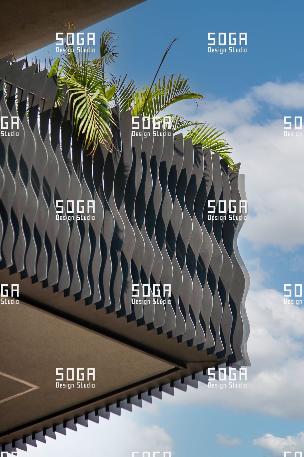
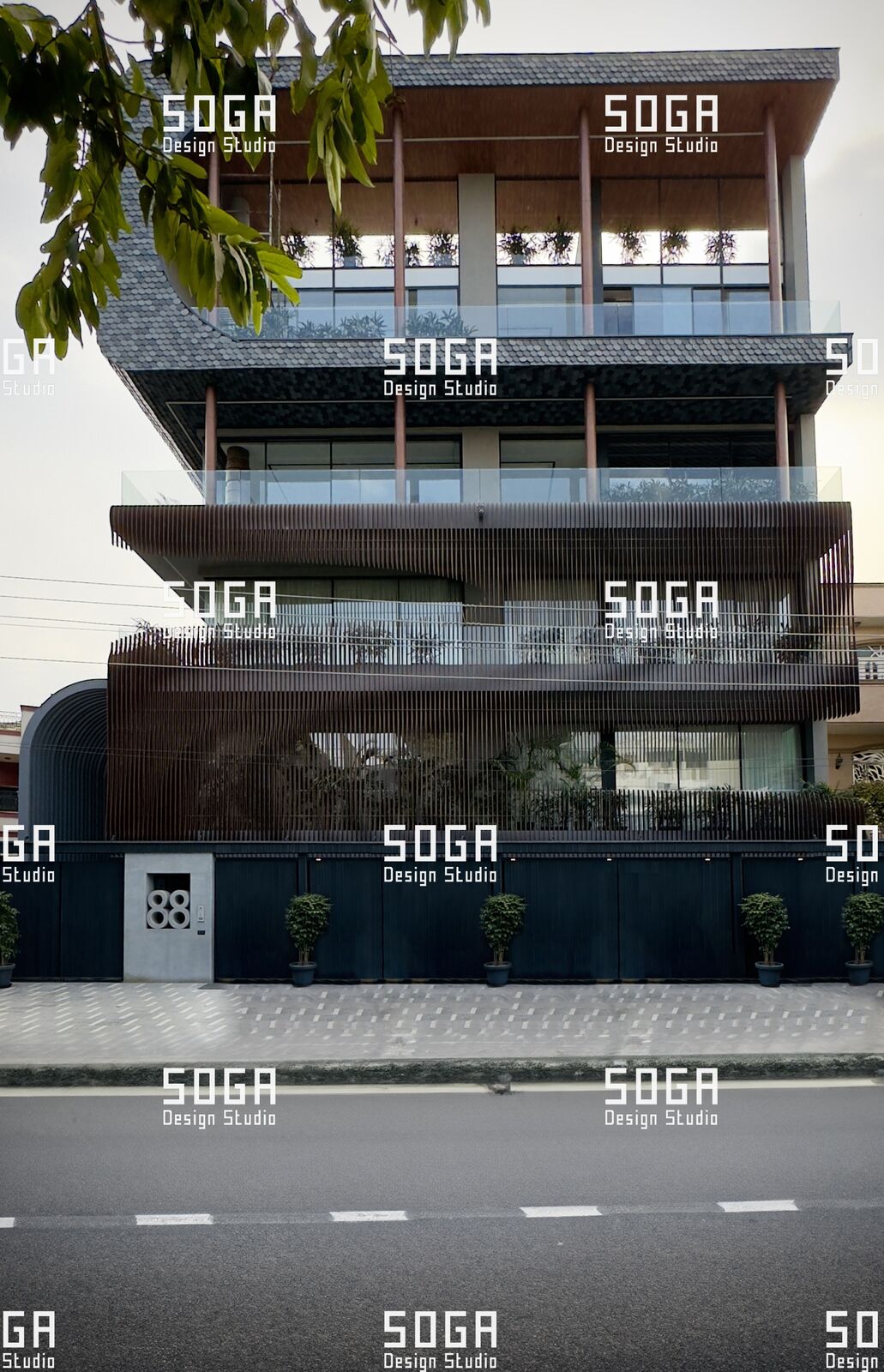
These are concept designs by SOGA Design Studio, produced as design visualisations rather than photographs of completed buildings.
Why Is The RCC Frame Never Where The Drawing Says It Is?
Because the codes permit it. ACI 117-10, the specification for tolerances for concrete construction, allows a building’s lines, surfaces, corners and arrises to be out of plumb by the lesser of 0.3% of the height or 25 mm up to 25.4 m, and by the lesser of 0.1% of the height or 150 mm above that. At 40 m, a 40 mm lean is a compliant frame, not a defective one.
IS 456:2000 is quieter on this than most people assume. Clause 11.1 gives tolerances on the shapes, lines and dimensions shown in the drawing — deviation from the specified cross-section of columns and beams of +12 mm / −6 mm, plus a set of footing tolerances — and it notes that these apply to concrete dimensions only, and not to the positioning of vertical reinforcing steel or dowels. There is no line in that table telling you how far the twelfth-floor slab edge may sit from the second-floor slab edge. That number lives in the project specification, or it does not exist at all.
So the honest starting position for a facade contractor in India is this: the frame is compliant and the frame is out. Those are not contradictory. A tower reaching 40 m can be 40 mm out of plumb, each slab section can be +12 mm / −6 mm, each formed surface can be ±19 mm on level before the shores come out, and the sum of those is what your bracket has to swallow before a single panel is hung.
Who absorbs the gap between structural tolerance and facade tolerance?
The bracket absorbs it physically. Commercially, somebody has to absorb it too, and that has to be written down before mobilisation. A facade setting-out tolerance of ±3 mm on a joint line cannot be delivered off a structure permitted ±25 mm, so the contract must state who pays when the surveyed deviation exceeds the bracket’s adjustment range — and what that range is, in millimetres, per axis. Left undefined, it becomes an argument at the fourteenth floor with a crane on standby.
| What is measured | Facade setting-out tolerance typically required | Deviation the structure is commonly permitted | Who closes the gap |
|---|---|---|---|
| Verticality of the facade plane over full height | ±3 to ±5 mm on the facade datum | Lesser of 0.3% of height or 25 mm up to 25.4 m; lesser of 0.1% or 150 mm above (ACI 117-10 §4.1) | Bracket out-stand adjustment (X axis) |
| Slab edge position in plan, floor to floor | ±3 mm from the facade grid | ±25 mm horizontal deviation of vertical elements (ACI 117-10 §4.2.1) | Bracket out-stand plus a slotted plate |
| Slab soffit level at the fixing line | ±2 to ±3 mm at the fixing point | ±19 mm on formed surfaces before removal of shores (ACI 117-10 §4.4.2) | Shim and packer stack (Z axis) |
| Column and beam section | Assumed nominal in the shop drawing | +12 mm / −6 mm (IS 456:2000 cl. 11.1) | Bracket out-stand, or a re-issued shop drawing |
| Cover to the outermost bar | Assumed nominal when siting the anchor | Nominal +10 mm / −0 mm (IS 456:2000 cl. 12.3.2) | Rebar scan, then re-site the anchor |
| Cumulative bow across a 30 m elevation | ±5 mm on the visible line | Not tabulated in IS 456; project specification only | Survey, then a decision — not a shim |
What Must A Pre-Installation Survey Measure, And To What Accuracy?
Four things: the position of every intended fixing line in three dimensions, the slab edge and soffit geometry at each of those lines, the condition of the concrete face where each anchor will go, and the single datum the whole facade will be set from. Anything less and the bracket family is a guess with a purchase order attached.
- Control datum. One facade datum established from the structural grid and carried up the building, re-verified at every third floor. It is never re-established from the slab you happen to be standing on, because that slab is one of the things being measured.
- Fixing-line survey. The X, Y and Z position of each bracket location, read to 2 mm or better with a total station, at not fewer than three points per structural bay.
- Slab edge profile. Edge position and edge squareness at every floor. A slab edge that has rolled outward by 15 mm at the top changes the out-stand, not the level, and the two are corrected by different parts of the bracket.
- Soffit condition. Depth of sound concrete, drop beams, service penetrations, and any patching, honeycombing or shutter-joint damage at the intended anchor position.
- Obstruction map. Down-take pipes, conduit cast into the slab edge, and the location of the outermost reinforcement layer wherever anchors are planned.
Accuracy matters more than density. Twenty points read to 10 mm are worse than eight points read to 2 mm, because 10 mm of survey noise consumes roughly a third of the adjustment a compact bracket gives you before the frame’s own deviation has been counted. Specify the instrument, the accuracy and the datum in the survey scope, and specify the deliverable as a deviation table per fixing line.
Issue the survey as a dated, signed document, and carry the deviations into the shop drawing as recorded values rather than as the phrase “within tolerance”. That phrase has never helped anyone size a shim stack. A works engineer needs the number, the fixing reference it belongs to, and the date it was read.
What Do You Do When The Survey Is Worse Than Your Adjustment Range?
You stop and choose, in this order: re-datum, change the bracket family, add approved local packing, or modify the structure. What you do not do is stretch the bracket you already bought by cutting its slots longer, because slot length is part of the bracket’s tested capacity and lengthening it voids the calculation it was accepted on.
- Re-datum the facade. If a whole elevation leans 40 mm one way, the cheapest correction is often to tilt the facade datum plane and split the error — 20 mm each way instead of 40 mm one way — provided the plan geometry, the parapet line and the ground-floor junction can all accept the shift.
- Move up a bracket family. A compact plate bracket giving 25 mm of out-stand adjustment is replaced by a three-axis bracket giving 90 mm. That is a cost and a lead-time decision, and because it lengthens the lever arm it goes back to the structural engineer before it goes to procurement.
- Local packing, approved. Steel packers to a stated maximum stack thickness and a stated maximum number of plates, with the fixing length increased to suit. The limit is set by the engineer, not by what happens to be in the van.
- Modify the structure. Cutting back a slab nib or casting a corbel is a structural alteration. It is designed and signed off by the project structural engineer before a breaker is switched on, and it is drawn on the as-built.
Any deviation that falls outside all four options is recorded and escalated the same day. An unrecorded 30 mm deviation at the fifth floor becomes a visible 30 mm step in a joint line read from the road, and by the time it is noticed the sequencing decision that would have absorbed it is four floors below. The programme logic that governs how a facade is built up an elevation is a separate discipline in its own right — see SOGA coin facade installation: sequencing, tolerance and site realities in India.
Which Bracket Family Buys How Much Adjustment In Each Axis?
Between roughly 15 mm and 150 mm depending on the family, and almost never the same amount in all three axes. Read the table by the axis you are short in, not by the bracket that looks strongest. Strength is a different question, answered by wind load and panel area — that argument is made in Facade Panel Wind Load India: Why Smaller Is Not Safer.
Fix the axis convention before anything else. X is out-stand, perpendicular to the elevation — the axis that absorbs lean and slab-edge roll. Y is horizontal along the elevation — the axis that absorbs grid drift. Z is vertical — the axis that absorbs slab level. Every drawing, every table and every site instruction on the job uses the same three letters, or you will lose a day per floor to translation.
| Bracket family | X — out-stand (mm) | Y — horizontal (mm) | Z — vertical (mm) | Where it earns its place |
|---|---|---|---|---|
| Fixed plate, single hole | 0 | 0 | 0 | Only on a proven cast-in line where the datum is already surveyed and accepted |
| Slotted plate, single horizontal slot | 0 | 20–40 | 0 | Grid drift on an accurate frame; the cheapest correction available |
| Slotted angle, two-way slots | 10–20 via packers | 25–50 | 20–40 | The common workhorse on Indian RCC. It runs out of X first, every time |
| Three-axis adjustable bracket, serrated interface | 40–120 | 30–60 | 40–80 | Out-of-true frames; the family a 40 mm lean usually forces you to |
| Threaded-rod / spindle bracket | 50–150, fine at 1–2 mm per turn | 0–20 | 0–20 | Where X is large and has to be dialled precisely, such as a curved set-out |
| Packer and shim stack behind a fixed bracket | 3–25, typically capped at three plates | 0 | 0 | Local correction only, to an approved maximum stack thickness |
| Site-welded bracket onto a cast-in plate | Free within the plate | Free within the plate | Free within the plate | Last resort. Needs a welding procedure, an inspector and full re-coating |
The last row is where projects go wrong quietly. Site welding buys unlimited adjustment and costs you the galvanised coating in roughly a 60 mm halo around every weld, plus a qualified welder, plus a hot-work and fume permit at height, plus a re-coating system that will never match the factory coating. If it is in the method statement from day one it is a legitimate technique. If it appears at the fourth floor because nothing else fits, it is a deviation dressed as a solution.

How Does Three-Axis Adjustment Actually Work On Site?
One axis at a time, in a fixed order, with each axis locked before the next is touched. The order that works is Z, then Y, then X: set the level off the datum, set the horizontal position off the grid, then set the out-stand off the facade plane. Reverse it and you re-do the out-stand every time the level moves.
- Z, vertical. Set by the bracket’s vertical slot, or by a shim stack under a fixed leg. Locked with a serrated washer or a serrated interface plate — never by friction alone on a smooth face.
- Y, horizontal. Set by the horizontal slot in the bracket plate, or by sliding the bracket along a cast-in channel. On a channel this axis is genuinely free, and that freedom is the channel’s single biggest advantage on site.
- X, out-stand. Set by the second plate, the spindle, or the packer stack. This is the axis that governs the visible facade plane, and it is the axis that is most often short.
Serrated interfaces exist because a bolted lap joint in a slotted hole relies on friction, and friction relies on a torque that nobody re-checks in year three. A serrated pair transfers vertical load in bearing on the serration, so a bolt that has relaxed still cannot let the bracket slide. Where the interface is smooth, that shear has to be carried by the bolt in bearing instead, and the hole edge distance in the bracket plate becomes a design item rather than a detailing habit.
Every adjusted bracket is torqued to the value on the drawing, marked with a torque stripe, and has its as-set X, Y and Z recorded against its bracket number. That record is what tells you, at the twentieth floor, whether the drift you are looking at is the frame or your own installation. It is also the only defence available when a joint line is questioned at handover.
Cast-In Channel Or Post-Fixed Anchor: Which Does Your Programme Allow?
Cast-in anchor channel is technically the better interface and it is programme-hostile. It must be fixed to the shutter before the pour, which means the facade contractor has to be appointed and the setting-out issued while the frame is still climbing. On most Indian projects the facade package is awarded after the frame has topped out, and that single fact settles the anchor type.
| Anchor type | What it needs before it can be used | Adjustment it gives | When it becomes impossible on a live site |
|---|---|---|---|
| Cast-in anchor channel | Facade setting-out issued before the pour; channel fixed to the shutter and surveyed; filler strip intact; a channel type carrying a current approval | Free sliding along the channel in one axis; zero in the other two | The frame is already cast. There is no route back |
| Cast-in headed stud plate | The same pre-pour coordination, plus the plate held flush and level with the shutter face | Zero. Site welding onto the plate is the only correction | The frame is already cast |
| Post-fixed torque-controlled expansion anchor | Sound concrete of the assumed grade; hole drilled to the approved diameter and depth; hole cleaned; calibrated torque wrench; edge distance and spacing per the product approval | None — the bracket provides all of it | Thin slab nib, edge distance below the approved minimum, or a cracked-concrete zone the approval does not cover |
| Post-fixed undercut anchor | All of the above, plus an undercutting tool and an operator trained on that tool | None | No clearance for the tool, or overhead work where it cannot be held true |
| Post-fixed bonded (chemical) anchor | Hole cleaned to the manufacturer’s stated regime; resin within its shelf life; base-material temperature inside the stated window; full cure before any load is applied | None | Wet or flooded holes, base temperature outside the window, or a programme with no room for the cure time |
| Concrete screw | Hole diameter held to a tight tolerance; a driver that will not over-run the seating | None | Where repeated removal and refitting is expected beyond the approved re-use count |
The commercial consequence is worth stating plainly: choosing cast-in channel is a decision made by the developer’s procurement programme, not by the facade engineer. If the facade package is not appointed before the third-floor pour, cast-in channel is off the table for the whole tower. India now has genuine domestic supply of both channel and post-fixed systems, which changes the lead-time argument without changing the sequencing one — the wider shift is set out in Designed in India, Engineered in India.

What Does A Post-Fixed Mechanical Anchor Need From The Concrete?
Five things it will not compromise on: concrete of at least the strength assumed in the design, a minimum edge distance, a minimum spacing from its neighbours, a minimum member thickness, and a stated effective embedment. Every one of those numbers comes from that anchor’s own approval document and the project structural engineer’s calculation. There is no universal figure, and anyone offering you one is guessing.
The design framework is EN 1992-4:2018 in the European system and Chapter 17 of ACI 318-19 in the American one. EN 1992-4 covers cast-in headed fasteners and anchor channels, post-installed mechanical fasteners including expansion, undercut and concrete screws, and post-installed bonded fasteners, under static, quasi-static, fatigue and seismic actions as well as fire, from a minimum size of M6 upward. Neither code replaces the product-specific approval — a European Technical Assessment or an evaluation report — which is where the actual millimetres live.
The single most consequential line in that approval is whether the anchor is qualified for cracked concrete. A slab edge in flexure, a zone near a support, or anywhere a crack can pass through the anchor’s breakout cone, is cracked-concrete territory whether or not a crack is visible today. An anchor qualified only for uncracked concrete, installed where the concrete later cracks, sheds capacity without announcing it. That determination comes from the frame design and the project structural engineer, never from a visual check at the fixing point.
What the works engineer actually controls is the installation, and it is controllable to the millimetre:
- Hole diameter and depth to the values in the approval, checked with a depth gauge rather than a tape mark on the drill body.
- Hole cleaning to the stated regime before the anchor is set.
- Setting torque applied once with a calibrated wrench, and the value recorded.
- Edge distance and spacing measured and recorded per anchor, not assumed from the drawing.
- No re-use of an abandoned hole, and no widening of a hole to correct a position error.
When Is A Chemical Anchor The Right Answer, And When Is It The Wrong One?
It is right where edge distances are tight, where the member is thin, or where the expansion force of a mechanical anchor would split the concrete. It is wrong where the hole cannot be cleaned, where the base-material temperature sits outside the resin’s stated window, or where the programme has no room for the cure.
Hole cleaning is the whole argument. A bonded anchor transfers load through a resin bond to the wall of the hole, and drilling dust left in that hole behaves as a release agent. Manufacturers publish a specific regime — a defined sequence of blowing and brushing with a stated brush diameter, or a hollow-drill dust-extraction system that cleans as it drills. Follow the regime printed in the approval for that specific resin. A different resin has a different regime and the two are not interchangeable.
Base-material temperature, not air temperature, governs the cure. A west-facing slab edge in Ahmedabad at three in the afternoon and the same slab edge at six in the morning are two different base materials with different working times and different cure times. In the Gulf, summer slab surface temperatures routinely push resins to the short end of their working time, and the resin goes off in the nozzle before the hole is filled. In a monsoon week, a hole that will not dry is a reason to stop, not a reason to proceed carefully.
The cure itself is not negotiable. Loading a bonded anchor before full cure is the failure that shows up months later as a bracket that has crept 2 mm, then 5 mm, with no visible cause. Build the cure time into the sequence — bracket set on day one, load applied on day two — rather than discovering it at four o’clock on a Saturday with a crane already booked.

Slab Edge Or Soffit: Which Face Should You Fix To?
On an Indian RCC frame the soffit is often the honest answer. The slab edge is the face everyone draws to, and it is also the face with the least concrete, the tightest edge distance, the most cast-in services and the most patching. The soffit, 150 mm back from the edge, is thicker, better compacted, further from the reinforcement congestion at the edge, and out of the weather.
| Consideration | Slab edge (vertical face) | Soffit (underside) | Which usually wins |
|---|---|---|---|
| Available edge distance | Bounded by slab thickness; a 150 mm slab leaves very little either side of the anchor | Governed by how far back from the edge you choose to fix | Soffit |
| Concrete quality at the anchor | Edge concrete is the most likely to be honeycombed, patched or spalled at the shutter joint | Generally well compacted once you are clear of the edge | Soffit |
| Reinforcement congestion | Edge bars, links and any edge-beam cage sit exactly where you want to drill | Bottom bars run in a known, scannable direction | Soffit |
| Cast-in services | Down-take pipes and conduit are commonly dropped at the slab edge | Fewer, and easier to scan for | Soffit |
| Load path | Direct: dead load is a shear on the anchor, wind a combined tension and shear | Dead load hangs from the anchor in tension — a larger anchor for the same panel | Slab edge |
| Access to install | Reachable from a cradle or a platform outside the facade line | Needs the operative under the slab, drilling overhead | Slab edge |
| Water | Anchor sits in the wetted zone and needs a drip above it and a sealed penetration | Sheltered, though the drip line above still has to be resolved | Soffit |
| Effect on the visible facade line | Short out-stand, short lever arm, less deflection to check | Longer out-stand and a longer lever arm; deflection must be calculated | Slab edge |
Read that table honestly and it says the soffit is better concrete and worse ergonomics, and that it costs you a larger anchor because the dead load now hangs in tension rather than bearing. The trade is worth making on a frame whose edge is patched, and not worth making on a clean edge with a generous nib. It is decided per elevation after the survey, and two elevations on the same building are allowed to differ.
Whichever face you use, the anchor penetration is a hole through the outer skin of the building and is treated as one. A soffit fixing sits under a drip that has to throw water genuinely clear of the bracket, and the reach arithmetic for that is worked through in Stop Rain Water Entering Balcony India With 692 mm Reach.

What Do You Do When The Drill Strikes Rebar?
You stop, you move, and you record. You do not cut the bar, you do not push through it, and you do not open the hole sideways to clear it. Cutting reinforcement is a structural alteration and only the project structural engineer can authorise it, in writing, before it happens.
The strike should be rare, because scanning comes first. A cover meter or a ground-penetrating scan run over the intended fixing line marks the bar positions before a drill is switched on. IS 456:2000 clause 12.3.2 gives a useful asymmetry here: the actual cover should not deviate from the required nominal cover by more than +10 mm, −0 mm. The outermost bar is therefore at least the nominal cover deep and may be up to 10 mm deeper — so a 40 mm nominal cover puts the first bar somewhere between 40 mm and 50 mm from the face, which a 90 mm embedment will pass straight through.
- Stop at first contact. A drill that suddenly slows and produces bright swarf has found steel, not aggregate.
- Move within the drawn tolerance. Shift the anchor in the direction the scan says is clear — typically 30 to 60 mm along the bracket slot — and re-check edge distance and spacing after the move, not before.
- Escalate when the move breaks a rule. If the new position falls outside the approved edge distance or spacing, it stops being an installer’s decision and goes to the structural engineer.
- Fill and draw the abandoned hole. Grout or resin it, and put it on the as-built, because the next trade will want to drill there.
- Record the strike against the bracket number. Three strikes on one elevation is either a scanning problem or a rebar-layout surprise, and both are worth knowing at floor four rather than floor fourteen.
How Is An Anchor Proved Once It Is In The Slab?
By a site proof-load test regime written into the project specification by the structural engineer, using the anchor manufacturer’s published data as the input. The number of tests, the proof load, the hold time and the pass criterion are all project-specific. SOGA does not set them, and no facade contractor should be setting them either — the structural engineer specifies, an independent testing house executes, and the results are witnessed and signed.
What the works engineer is responsible for is making that regime physically possible: leaving accessible anchors for the first-off test, providing clearance for the reaction frame, sequencing the testing before the panels go on rather than after, and keeping the concrete cube results and the anchor batch records where the tester can actually see them on the day.
A single failure is not a single failure. If one anchor on an elevation will not hold its proof load, the honest reading is that the whole population it came from is in question — same operator, same drill, same batch of resin, same zone of concrete. The correct response is to widen the sample, not to replace that one anchor and carry on. Widening the sample costs a day. The alternative costs a facade.
The test methods themselves are standardised. ASTM E488, covering the strength of anchors in concrete elements, and ASTM E1512, covering bond performance of bonded anchors, are the usual references for how a test is conducted. What they do not supply is the acceptance criterion for your project, which remains the engineer’s to write.

What Isolation Does A Steel Bracket On An Aluminium Carrier Need?
A physical separator at every point where the two metals touch, and a fastener more noble than both. A galvanised steel bracket bolted directly onto an aluminium carrier in a coastal or Gulf atmosphere will corrode the aluminium carrier at the interface, and the interface is the one place nobody can inspect once the panel is on.
ISO 9223:2012 classifies atmospheric corrosivity from C1, very low, through to CX, extreme, driven by the temperature-humidity complex, sulphur dioxide pollution and airborne salinity. Marine exposures commonly sit at C4 to C5. That classification should drive the entire fixing specification: a Chennai seafront plot, a Mumbai western-edge plot and a Dubai coastal plot are not the same problem as an inland site in Jaipur, and the same bracket schedule should not be issued for both.
| Exposure | Typical ISO 9223 category | Bracket | Fastener | Isolation at the interface |
|---|---|---|---|---|
| Inland, dry, low pollution (Jaipur, inland Rajasthan) | C2–C3 | Hot-dip galvanised steel to IS 4759 | Zinc-plated or A2 stainless | Isolation washer at the bolt, separator where faces bear |
| Urban, high pollution and humidity (Delhi NCR, Ahmedabad) | C3–C4 | Hot-dip galvanised steel, coating mass stated on the drawing | A2 (304) stainless | Full separator pad plus isolation bush and washer |
| Coastal India (Chennai, Mumbai, Kochi) | C4–C5 | A4 (316) stainless, or galvanised steel with a duplex coating system | A4 (316) stainless | Full separator, isolation bush, sealed penetration |
| Gulf coastal (Dubai, Abu Dhabi, Doha) | C5–CX | A4 (316) stainless as the default | A4 (316) stainless | Full separator, isolation bush, and a documented inspection route |
| Tropical SE Asia (Singapore, Kuala Lumpur) | C3–C5 by distance from the sea | A4 (316) stainless near the coast, galvanised inland | A4 (316) stainless | Full separator plus a drained cavity behind the bracket |
Where hot-dip galvanising is the answer, specify it properly rather than writing the word on a drawing. IS 4759 sets a minimum average coating mass of 610 g/m² for fabricated articles from roughly 5 mm thickness upward, which is about 85 microns of zinc; read the exact grade against your own section thickness from the table in the standard. Put the number on the bracket drawing and check it on delivery with a coating gauge, because a bracket that arrives at 45 microns will not tell you it is wrong until year six.
Two rules decide the rest. First, area, not nobility alone, decides the fastener: a small stainless bolt through a large galvanised plate is fine, because the small noble part is the cathode; a small galvanised bolt through a large stainless plate is the reverse and eats the bolt, which is exactly where you least want a failure. Second, an aluminium bracket in direct contact with damp concrete is attacked by the alkalinity of the cement matrix, so an aluminium bracket bearing on an RCC face needs a bituminous or polymer separator regardless of the atmosphere outside.

Is Movement Taken At The Bracket Or At The Panel?
Both, and they must not fight each other. The bracket takes movement between the building and the facade’s carrier structure. The panel joint takes movement between one panel and the next. Fix the bracket line rigidly and leave the panel joint generous and you have built a facade that loads its own brackets in shear every afternoon.
The convention that works is one fixed point per carrier run and sliding points everywhere else. The fixed point defines where the run does not move; every other bracket carries weight but lets the run slide along its length. A 6 m aluminium carrier through a 45 K temperature swing travels about 6 mm end to end — more than enough to bind a slotted hole that was bolted hard against the shank on a cool morning.
Steel moves roughly half as much: about 12 × 10⁻⁶ per kelvin against an aluminium carrier’s 23 × 10⁻⁶, so the same 6 m run in steel travels about 3 mm. A steel bracket carrying an aluminium carrier means two materials moving at different rates across one interface, which is one more reason the sliding point has to be genuinely free rather than nearly tight.
The panel-to-panel joint arithmetic — how wide the visible gap has to be, and what it does across a season — is a separate calculation with different inputs, and it belongs to the panel rather than to the bracket. Do not size the joint from the bracket movement, and do not size the bracket from the joint width. The two are independent and both are required.

Which Fixing Failures Are Silent Until They Are Not?
Four, in rising order of how long they stay hidden. A badly torqued anchor announces itself in weeks. An over-shimmed stack announces itself in a season. An anchor in a cracked-concrete zone announces itself in a storm. An unrecorded deviation announces itself at handover, when it is somebody’s fault and nobody’s budget.
- Panel detachment. Almost never the panel, and almost never the bracket plate. It is the anchor, or the bolt through the anchor, or a shim stack that has crushed. A load path only has to fail at its weakest link, and the weakest link is the smallest steel section in it.
- Anchor in cracked concrete. An anchor qualified only for uncracked concrete, sited near a support or in a flexural zone, holds its proof load on day one and loses capacity when the crack opens under load. Nothing visible on site tells you it has happened.
- Over-shimmed stack. Packers beyond the approved number and thickness turn a bearing joint into a spring. It creeps, the bolt relaxes, the bracket rotates, and the facade line drifts outward a millimetre at a time.
- Bimetallic interface with a missing separator. One washer left out of a bag of two hundred, in a C5 atmosphere, at a location nobody will ever inspect again.
- Unrecorded deviation. The cheapest failure to prevent and by far the most common. A bracket set 12 mm off its drawn position and never written down becomes a mystery three floors later, when the joint line steps and nobody can say where the step began.
None of these is exotic, and all of them are caught by the same two habits: scan and survey before you drill, and record every bracket as set. Those habits cost about an hour per floor. The alternative is a scaffold going back up after handover, which is the most expensive hour in the industry.

What Does The Fixing Layer Cost In India, And Where Does Skimping Show?
The bracket and anchor package is a small fraction of a facade budget and a large fraction of its risk. Indicative 2026 India ranges, for first-pass budgeting only: a three-axis adjustable galvanised bracket set — bracket, anchors, isolation components and fixings, supplied and installed — runs roughly ₹950 to ₹2,800 per fixing position, driven by bracket size, anchor type and access. Cast-in anchor channel sits around ₹600 to ₹1,500 per running metre supplied, before the shutter-fixing labour and the pre-pour survey. Rebar scanning and setting-out survey of an elevation adds roughly ₹20 to ₹50 per square metre. Site proof-load testing typically runs ₹1,500 to ₹4,000 per test position including witnessing. An itemised estimate is issued per project; these bands are for a budget, not for an order.
Where projects save money and pay for it later: dropping the survey saves about ₹20 per square metre and costs a bracket-family change; dropping the scan saves an afternoon and costs a rebar strike plus a structural query; ordering the cheapest bracket family before the survey exists saves nothing at all, because the second order is the one that gets installed. Every one of those is a decision taken before mobilisation, which is precisely why the survey comes first.
The fixing layer is where a facade design either becomes buildable or becomes an argument. The wider method — how a pattern becomes a set of parts with a load path, a tolerance strategy and a fabrication route — is set out in parametric facade design in India, and the panel-level consequences of getting the interface right are visible in the complete guide to circular parametric metal panels.
Brackets and anchors are one of seven inspection points on a house elevation. The full stage-by-stage elevation site checklist.
Brackets are one layer of a larger load path. For the wider picture see wind load, MS framework and anchoring.
Related Reading
- Facade Panel Wind Load India: Why Smaller Is Not Safer
- SOGA Coin Facade Installation: Sequencing, Tolerance and Site Realities in India
- SOGA Coin Facade: The Complete Guide to Circular Parametric Metal Panels
- Stop Rain Water Entering Balcony India With 692 mm Reach
- Designed in India, Engineered in India: How Parametric Facade Systems Became Manufacturable
- Parametric facade design in India
Frequently Asked Questions
How much adjustment should a facade fixing bracket have on an Indian RCC frame?
Enough to cover the surveyed deviation with margin, which on a typical Indian RCC frame means a bracket family offering at least 40 to 90 mm in the out-stand axis. Set the range from the actual survey rather than a rule of thumb: a frame surveyed at 40 mm out of true needs more than a slotted angle can give, and finding that out after the brackets arrive costs a lead time.
Can you still use a post-fixed anchor if the cast-in channel was missed?
Yes in most cases, and it is the normal situation on Indian projects where the facade package is awarded after the frame tops out. The post-fixed anchor must be qualified for the concrete condition at that location, including cracked concrete wherever the structural engineer determines cracking is possible, and its edge distance, spacing and effective embedment come from the product approval and the engineer’s calculation, not from a standard detail.
Is it better to fix a facade bracket to the slab edge or the soffit?
The soffit is often the better concrete: further from edge congestion, better compacted, sheltered from weather, and away from cast-in down-take pipes. It costs a larger anchor, because the dead load hangs in tension rather than bearing, and it costs overhead drilling access. Decide per elevation after the survey; two elevations on the same building can legitimately be detailed differently.
What accuracy does a pre-installation facade survey need?
Read each fixing line to 2 mm or better with a total station, at not fewer than three points per structural bay, all referenced to a single facade datum carried up the building and re-verified every third floor. Ten millimetres of survey noise consumes about a third of a compact bracket’s adjustment before the frame’s own deviation has been counted at all.
Who signs off that a facade anchor is structurally adequate?
The project structural engineer. The anchor manufacturer publishes tested capacity in the product approval; the facade contractor installs to that approval and records what was installed; an independent testing house executes the specified proof-load regime. SOGA designs and details the facade system and its interface with the structure. Structural adequacy of the anchor into the concrete is signed off by the project structural engineer.
Get The Fixing Layer Detailed Before You Mobilise
SOGA Design Studio details facade systems down to the bracket, the anchor and the shim stack, and issues the survey scope that has to run before any of it is ordered. If you are pricing a facade against an RCC frame you have not measured yet, send us the elevation, the frame drawings and the programme dates, and we will tell you which bracket family the job actually needs and what the survey has to catch. Anchor design into the concrete is confirmed with your project structural engineer. Write to [email protected].